


Page 8 of 29
Copyright © 2010 Linn Products Ltd.
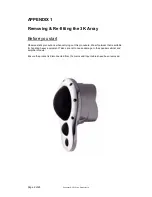
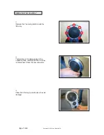
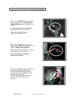
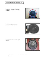
RE-FITTING THE 3K
ARRAY
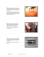
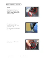
1.
Carefully locate the 3K Array in position
ensuring the rear connector locates in
position when fitted.
2.
Fit the top mounting bolt first to hold the 3K
Array in position.
Gently move the 3K Array from side to side
to ensure the gap between the 3K Array
chassis and the loudspeaker cabinet is
evenly spaced.
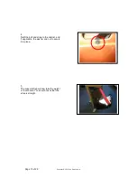
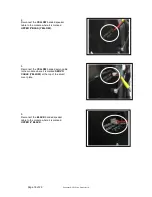
3.
Fit the remaining 6 screws to secure the 3K
Array in position.


