background image


feature by depressing and holding the override switch of microphone. Pushing 
in the button marked 13/67. Will increase power form 1 watt to 25 watts on 
Channels 13 and 67 only. Pushing the PTT button will suspend all receiving 
functions including scanning. Trans mission will occur on channel shown at 
instant PTT is pushed. Upon release of PTT, receive function will resume and 
scanning functions will resume 5 seconds after no signal is received. PTT will 
not operate if transceiver is on weather or vacant (null)  
  Channels in program model. (If PTT key is pushed during the time a signal is 
being received, 

a short beep tone will sound.) Transmission may continue. (If 

PTT is pressed continuously for 5 minutes, 3 short beep tones will be heard 
and transmission will be terminated until PTT is released and repressed.)


4.4


Keypad


The Keypad has various keys (push buttons) which control the functions of the 
transceiver.  


A. 

USA/International 

Pressing the USA/International key will select either USA or International 
channel. USA or International will be indicated on the liquid crystal display. 
USA channels include 01-28, 60- 74, 77-88. International channels include 
01- 28, 37, 39, 60- 74, 77-88, M0, M1, and M2. M1 and M2 are not authorized 
for use in USA waters. 


B. 

High or Low power 

Pressing the normal key allows any USA / Intl. Channel to be selected by 
resetting the up or down keys. One press will raise or lower the channel 
number by 1. Holding either the up or down key for more than 1.5 seconds will 
speed up the channel selection process to 4 steps per second. Channel 
number will be indication on LCD. 


C. 

Normal All Channel Scanning 

With transceiver in normal model, normal key pressed and normal indicated, 
press “scan” key  to activate scanning. Transceiver will scan all channels in 
either USA or International list. (M0, M1, M2 cannot be scanned). They can be 
selected manually in normal model. “Scan” will be indicated on liquid crystal 
display. 

Содержание SEALAB LT2001

Страница 1: ...s static interference or circuit failure Other equipment is available for marine navigation and safety and communications should never be relied on for these important marine procedures In compliance with certain state laws Link Tech The manufacturer of the equipment you have purchased is required to provide suitable space in your Operation Manual to enable you to record the model and serial numbe...

Страница 2: ... 1045 Main Street P O Box N B Moncton N B E1C 8R2 506 851 6525 Ontario Regional Office 9 th Floor 55 St Clair Ave East Toronto Ont M4T 1M2 416 973 8215 Prairies and Northwest Territories Regional Office Room 200 386 Broadway Ave Winnipeg Man R3C SY9 204 983 3182 Quebec Regional Office Suite 306 715 Peel Street Montreal Quebec HSC 4S2 514 283 2307 B C Yukon Regional Office Suite 1700 800 Burrard St...

Страница 3: ... by multiplying the number of stations to be modified by 35 00 When adding stations to be added by 35 00 Questions about fees may be directed to the FCC S Private Radio Bureau Consumer Assistance Branch Gettysbury PA phone 717 337 1212 Other FCC Information The LT2001 radiotelephone meets all applicable sections of FCC Rules Part 80 The following data pertaining to the LT2001 is helpful when filli...

Страница 4: ...ca tion Number 477822104V 2 UNPACKING Equipment Supplied Radio Mounting Bracket Two mounting Knobs Microphone Microphone hanger clip Power cord with fuse Instruction Manual Warranty Card License Application form for USA Unpack all items carefully Retain the carton all packing materials for possible future use 3 INSTALLATION Choose a location for your radio that is free from direct water spray Rain...

Страница 5: ...o your boat battery Choose a point which is able to handle at least 6 amps Your best location would be the switched side of your ignition switch If you must extend the power leads keep wiring as short as possible since long wires can reduce the transmitter performance Use 10 wire size for up to 10feet and size 8 for up to 25 feet Be sure to connect the red fused lead to the positive terminal and t...

Страница 6: ...Talk switch is pressed for over 5 minutes continuously transmission is forcibly inhibited 4 0 OPERATING CONTROLS AND FUNCTIONS When your transceiver is first turned on it wi ll begin operating in the following condition 1 All liquid crystal display segments are lighted up indicated for about 1 second 2 Normal channel model Channel 01 3 Programmable memory 10 Channel Scan erased 4 Weather Channel 0...

Страница 7: ...ons which control the functions of the transceiver A USA International Pressing the USA International key will select either USA or International channel USA or International will be indicated on the liquid crystal display USA channels include 01 28 60 74 77 88 International channels include 01 28 37 39 60 74 77 88 M0 M1 and M2 M1 and M2 are not authorized for use in USA waters B High or Low power...

Страница 8: ...p or down key to select the desired weather channel Total 10 weather channel from 00 to 99 are available Press normal key to terminate the weather channel function and return back to normal channel function F M Channels Mode Press M key to activate M channel function M indicator is shown Channel number show 00 Press M key again to access next M channel Channel number shows 01 Press M key again wil...

Страница 9: ...crystal display If the transceiver hears a signal the scanning function will cease and the receiver will stay on that channel for four 4 seconds minimum or as long as the signal continues During this stop scan period the scanning function can be suspended by pressing the scan key again The scan indication will flash continuously Press scan key once again to reactivate scanning Press normal key to ...

Страница 10: ...ays monitor before transmitting Never interrupt emergency communications 6 2 Channel 13 Operation Communications on Channel 13 by regulation can only concern navigation at docks and bridges Transmission on Channel 13 is automatically limited to low power However in emergencies or blind river bends pushing the 13 67 override portion of the PTT will raise the power to 25 watts Use and power limitati...

Страница 11: ...xample CH 24 157 200 MHz transmit and 161 800 MHz receive USA mode NOTE All channels are factory programmed in accordance with FCC USA and IC Canada and International regulations Mode of operation cannot be altered from simplex to duplex or vice versa The manufacturer is not responsible for any radio or TV interference caused by unauthorized modifications to this equipment Such modifications could...

Страница 12: ...8 MAINTENANCE Link Tech products are maintained by highly skilled and trained technical personnel using the latest electronic equipment TROUBLESHOOTING CHART SYMPTOM PROBABLE CAUSE REMEDY Radio fails to power UP No DC voltage to the radio or blown fuse Check power cable for DC voltage or replace the 7A fuse with length 31 8mm diameter 6 35mm Radio blows fuse upon connection to power supply Reverse...

Страница 13: ... purchaser whenever incurred in connection with this warranty will pay removal or reinstallation charge A copy of the original sales receipt to establish date of purchase must accompany all claims under this limited warranty This limited warranty does not extend to equipment which has been improperly installed including those units that have been damaged due to reverse polarity operated subjected ...

Страница 14: ...nditions in which vessels operate weather sea conditions time signals notices to mariner hazards to navigation Betw een One way broadcast from coast to ship stations Note Currently used for Class C EPIRB emergency signals Channel 17 State Control Vessels State and local government Use Coordination regulation and control of boating activities and the rendering of assistance to vessels Between Ship ...

Страница 15: ...77 is limited to communications to and from commercial pilots concerning the movement and docking of vessels Note Channels 11 12 13 and 14 are used for vessel traffic service on the Great Lakes St Law rence Seaway and designated major ports Marine Operator Channels 24 25 26 27 28 84 85 86 87 88 Vessels Any Use To place a telephone call to any location in the world or to a vessel outside of your tr...

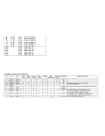
Страница 16: ...350 161 950 161 950 D D HI LO 28 157 400 162 000 161 950 D D HI LO 37 157 850 Intl Only 157 850 S HI LO 39 157 950 Intl Only 157 950 S HI LO This page contains a comprehensive list of channels available in the transceiver for transmit and receive as indicated USA and International use You may use only those channel authorized by the regulatory authorities in the waters of the country in which you ...

Страница 17: ...increased to 25 watts on PTT Not currently assigned for USA or International use WEATHER RECEIVER ONLY CHANNELS TX RX FREQ TX RX FREQ CH FREQ USA INTL CH FREQ USA INTL 00 163 275 163 275 05 162 450 162 450 01 162 550 162 550 06 162 500 162 500 02 162 400 162 400 07 162 525 162 525 03 162 475 162 475 08 161 650 161 650 04 162 425 162 425 09 161 775 161 775 This page contains comprehensive list of c...

Страница 18: ...50 161 850 Public Correspondence 26 157 300 161 900 Public Correspondence 27 157 350 161 950 Public Correspondence 28 157 400 162 000 Public Correspondence Please Note Channels 13 and 67 are limited to 1 watt except as overridden When necessary and allowable by PTT Channel 70 reserved for digital selective calling U S A CHANNEL AUTHORIZATION CH TX FREQ RX FREQ AUTHORIZED USE 63a 156 175 156 175 Pu...

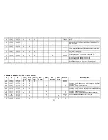
Страница 19: ...ercial Non Comm Safety Ship Movement Public Corres Area of OP Notes and Remarks 1 156 050 160 650 X PC 2 156 100 160 700 X PC 3 156 150 160 750 X PC 4A 156 200 156 200 X X X PC Canadian coast guard search and rescue 4A 156 200 156 200 X X X EC Commercial fishing only 5A 156 250 X 6 156 300 N A X X X X All areas May by used for search and rescue between ships and air 7A 156 350 156 350 X X X All ar...

Страница 20: ...t Guard and non Canadian Coast Guard stations only 23 157 150 161 750 X X PC Also inland waters of British Columbia Yukon 24 157 200 161 800 X X All areas 25 157 250 161 850 X X PC Also assigned op in Lake Winnipeg area 25B N A 161 850 X AC Continuous Marine Broadcast CMB service 26 157 300 161 900 X X X All areas 27 157 350 161 950 X X AC GL PC CANADIAN CHANNEL AUTORIZATION Continued CH TX RX Int...

Страница 21: ...7 156 875 156 875 X X X X Pilot age on Pacific Coast Port op only in St Lawrence River Great Lake areas with 1 watt maximum power 78A 156 925 156 925 X X X EC PC CANADIAN CHANNEL AUTORIZATION Continued CH TX RX Inter Ship Ship Shore Comm ercial Non Comm Safety Ship Movement Public Corres Area of OP Notes Remarks 79A 156 975 156 975 X X X EC PC 80A 157 025 157 025 X X X EC PC 81A 157 075 157 075 X ...

Страница 22: ...C Continuous Marine Broadcast CMB Service EC East Coast Includes NL AC GL and Eastern Arctic Areas NL Newfoundland and Labrador AC Atlantic Coast Gulf and St Lawrence River up to and including Montreal GL Great Lakes including St Lawrence above Montreal WC West Coast Pacific Coast Western Arctic and Athabasca Mackenzie Watershed areas PC Pacific Coast All areas Includes East and West Coast areas ...

Отзывы: