background image

800 AMP TANDEM MIG TORCH

GENERAL DESCRIPTION 

The Tandem MIG 800 Amp Welding Torch is
designed to deliver two wire electrodes to a single
weld pool. The wire electrodes are electrically isolated
from one another providing independent parameter
control of both electrodes. The torch has two separate
wire spacing options. The torch is designed primarily
for robotic applications utilizing wire electrodes in the
diameters of .035 through .062 inches. Torch ratings
are based on the use of shielding gas mixtures con-
taining a minimum of 82% argon gas.

The torch is designed for easy maintenance. 
The aluminum construction of the gooseneck outer
jacket and mounting /clamping assemblies defines the
lightweight low profile of the torch. The long goose-
neck design is provided for ease of robot program-
ming for access to restricted welding joints.
A single water-cooling source to circulate water
through the nozzle assembly establishes torch cool-
ing. The aluminum mounting and clamping assembly
serves as an added cooling feature providing a heat
sink to draw heat from the contact tip area and goose-
necks.

The torch may be operated as either a Tandem con-
figuration with two wire electrodes, or as a single wire
torch for special applications. Because of the size of
the Tandem MIG nozzle, during single wire operation
gas delivery through both diffusers is required. 

TORCH MOUNTING

The torch mounting arm is an integral part of the torch
mounting and clamping assembly, and should not be
removed or altered. The mounting arm is designed to
place the welding arc at the center line of a robot
mounting plate for programming ease. The arm is fur-
nished with a .647" hole for inserting a S22637 torch
mounting locking wedge. The mounting wedge is
designed to secure the torch to a common .75 " diam-
eter torch collision sensor shaft. 

Due to the weight of the torch and rapid movement of
many robotic applications it is recommended that a
rigid mount be used to secure the torch to a robot
arm. The rigid mount S22693-172 is to be used in
conjunction with robot collision sensing software.

NOTE:

The S22693-172 rigid mount is a dummy colli-

sion sensor. It is not designed to sense a torch colli-
sion. For proper operator and equipment protection
the S22693-172 rigid mount should only be used in
conjunction with robotic arm collision sensing soft-
ware.

For hard automation applications and for use with
robots that do not have collision sensing software, a
heavy-duty collision sensor is recommended
(M17809).

The collision sensor must be of proper rating to
withstand the high inertia stopping and starting associ-
ated with robot high-speed motion without tripping the
sensor.

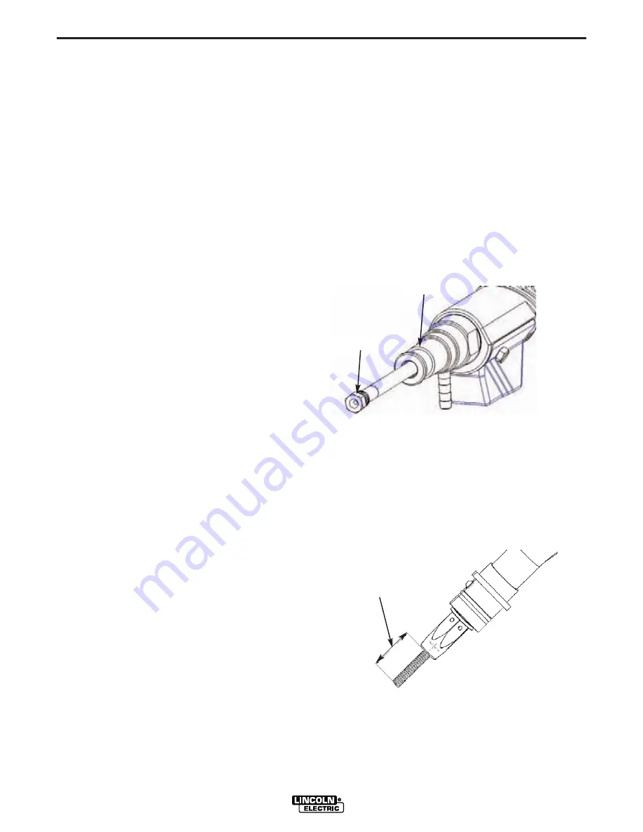
LINER INSTALLATION 

1.  Lay the torch and cable on a flat surface and

extend cables straight. 

2.  Remove contact tip and diffuser.
3.  With cables straightened, loosen 3/8" liner nut

from power pin. Grip liner with pliers and slowly
remove.

4.  With dry compressed air blow cable cavity free of

any accumulated dust or filings.

5.  Feed replacement liner through cable assembly

using short strokes to avoid kinking. Twist liner
clockwise if necessary.

6. Seat liner retainer O-ring to inside shoulder  bore

of power pin by tightening the 3/8" liner nut.

7.  Replace diffusers, tighten securely.
8.  With liner extending through torch body (contact

tip removed), trim liner to a 5/16" length.

9.  Remove any burr from end of liner that may

obstruct wire feeding.

10.  Replace contact tip and gas nozzle. 

A-2

INSTALLATION   

A-2

Power Pin

3/8" Liner Nut 

5/16 "
Extension

Содержание TANDEM MIG 800

Страница 1: ...bruary 2005 Safety Depends on You Lincoln arc welding and cutting equipment is designed and built with safety in mind However your overall safety can be increased by proper installation and thought ful operation on your part DO NOT INSTALL OPERATE OR REPAIR THIS EQUIPMENT WITHOUT READING THIS MANUAL AND THE SAFETY PRECAUTIONS CONTAINED THROUGHOUT And most importantly think before you act and be ca...

Страница 2: ...R WEARERS SHOULD CONSULT WITH THEIR DOCTOR BEFORE OPERATING Read and understand the following safety highlights For additional safety information it is strongly recommended that you purchase a copy of Safety in Welding Cutting ANSI Standard Z49 1 from the American Welding Society P O Box 351040 Miami Florida 33135 or CSA Standard W117 2 1974 A Free copy of Arc Welding Safety booklet E205 is availa...

Страница 3: ...ical earth ground 3 f Maintain the electrode holder work clamp welding cable and welding machine in good safe operating condition Replace damaged insulation 3 g Never dip the electrode in water for cooling 3 h Never simultaneously touch electrically hot parts of electrode holders connected to two welders because voltage between the two can be the total of the open circuit voltage of both welders 3...

Страница 4: ...event the welding sparks from starting a fire Remember that welding sparks and hot materials from welding can easily go through small cracks and openings to adjacent areas Avoid welding near hydraulic lines Have a fire extinguisher readily available 6 b Where compressed gases are to be used at the job site special precautions should be used to prevent hazardous situations Refer to Safety in Weldin...

Страница 5: ...propriés et non inflammables 4 Des gouttes de laitier en fusion sont émises de l arc de soudage Se protéger avec des vêtements de protection libres de l huile tels que les gants en cuir chemise épaisse pan talons sans revers et chaussures montantes 5 Toujours porter des lunettes de sécurité dans la zone de soudage Utiliser des lunettes avec écrans lateraux dans les zones où l on pique le laitier 6...

Страница 6: ... below for future reference This information can be found on your machine nameplate Product _________________________________________________________________________________ Model Number ___________________________________________________________________________ Code Number or Date Code_________________________________________________________________ Serial Number__________________________________...

Страница 7: ... 4 Operation Section B Electrodes and Equipment B 1 Making a Weld B 1 Avoiding Wire Feeding Problems B 1 Shielding Gas Delivery B 1 Air Blast Cleaning B 1 Nozzle Reaming B 2 Anti spatter Spray B 2 Maintenance Section C Contact Tip Replacement C 1 Liner Replacement C 1 Contact Tip Alignment C 2 Torch Dimensional Print C 3 Torch Alignment Tool L10430 1 Dimensional Print C 4 C 5 Trouble Shooting Sect...

Страница 8: ...S22693 124 S22693 133 Torch Cable length 10 ft cable assembly 8 ft cable assembly 6 ft cable assembly 4 ft cable assembly 12 ft cable assembly Shipping weight 28 6 lbs 25 2 lbs 21 8 lbs 18 4 lbs 32 0 lbs Minimum 35 scfh electrode 70 scfh total Maximum 70 scfh electrode 140 scfh total Flow rate Minimum 0 45 gal min Flow pressure Minimum 40 psi 0 035 to 0 062 diameter Trail Electrode size 0 035 to 0...

Страница 9: ...ed with a 647 hole for inserting a S22637 torch mounting locking wedge The mounting wedge is designed to secure the torch to a common 75 diam eter torch collision sensor shaft Due to the weight of the torch and rapid movement of many robotic applications it is recommended that a rigid mount be used to secure the torch to a robot arm The rigid mount S22693 172 is to be used in conjunction with robo...

Страница 10: ...ding gas delivery must be provided for both the lead and trail wire electrodes Gas is delivered to the diffuser area through the unicable conductor cable attached to each wire feeder A 10 inch gas hose assembly with 5 8 18 barred inert gas fitting is provid ed with the wire feeder The fitting is to be threaded into the wire feeder female gas outlet fitting The gas hose should be slid on to the bar...

Страница 11: ...ndersized contact tip may be required For 035 dia wire use a 030 contact tip and for 045 dia use a 040 contact tip WIRE STRAIGHTENERS Torch goosenecks have a 22 degree bend for joint accessibility The bend provides a wire cast condition ing that forces the welding wire against the contact tip for positive electrical contact If selected wire packag ing counters the effect of the bent goosenecks a w...

Страница 12: ...by observing the following procedures 1 Do not use a torch with cables that are longer than necessary 2 Do not kink or pull the torch cables around sharp corners 3 Keep torches cables as straight as possible or pro vide a gradual bend in the cables when welding or loading new wire 4 Protect cables from rubbing against sharp surfaces during operation 5 Use only clean rust free electrodes Protect el...

Страница 13: ...n the nozzle Anti spatter should not be applied through the air blast line Only dry air should be used for air blast functions Anti spatter may be applied to the interior of the noz zle from an external sprayer The M18426 1 reaming station comes equipped with an external spraying sta tion for this purpose Care should be taken to apply the right amount of anti spatter to the internal area of the no...

Страница 14: ...iffusers nozzle insulator and retainer 4 Lift upper portion of clamping assembly from lower slide back the black plastic back housing to expose gooseneck to unicable connection 5 Free the connection form the clamping assembly and with one 1 and one 3 4 wrench unscrew gooseneck from unicable brass junction fitting 6 Replace damaged gooseneck with replacement gooseneck making sure that the gooseneck...

Страница 15: ...1 Remove torch from automated equipment 2 Remove torch nozzle assembly 3 Select desired contact tip spacing by pivoting front alignment block of alignment fixture to correct spacing Two wire spacings are provided 5 16 standard and a 3 8 wide 4 With retainer diffusers and contact tips in place insert a straight portion of welding wire into each contact tip to simulate a 5 8 wire extension past the ...

Страница 16: ...C 3 MAINTENANCE C 3 800 AMP TANDEM MIG TORCH S22693 XXX MIG 800 amp Torch All dimensions in inches Bracketed dimensions are in millimeters ...

Страница 17: ...C 4 MAINTENANCE C 4 800 AMP TANDEM MIG TORCH L10430 1 Torch Alignment Tool Consisting of the following three parts 1 Base dimensions Part number L10430 3 2 Check Block dimensions Part number L10430 2 ...

Страница 18: ...C 5 MAINTENANCE C 5 800 AMP TANDEM MIG TORCH L10430 1 Torch Alignment Tool 3 Holding block dimensions Part number L10430 4 ...

Страница 19: ...POSSIBLE CAUSE lists the obvious external possibilities that may contribute to the machine symptom Step 3 RECOMMENDED COURSE OF ACTION This column provides a course of action for the Possible Cause generally it states to contact your local Lincoln Authorized Field Service Facility If you do not understand or are unable to perform the Recommended Course of Action safely contact your local Lincoln A...

Страница 20: ...1 Loose worn or incorrect drive rolls 2 Torch cable kinked or liner worn 3 Wire pay off dispenser malfunction ing 1 Keep cable assembly as straight as possible Inspect cable and replace if necessary 2 Check for any obstructions in cable assembly Check liner replace if nec essary 3 Be sure the wire diameter being used matches the drive rolls and guide tubes size 4 Replace contact tip 1 Remove dirt ...

Страница 21: ...NOTES 800 AMP TANDEM MIG TORCH ...

Страница 22: ...NOTES 800 AMP TANDEM MIG TORCH ...

Страница 23: ...electrically live parts or electrode with skin or wet clothing Insulate yourself from work and ground No toque las partes o los electrodos bajo carga con la piel o ropa moja da Aislese del trabajo y de la tierra Ne laissez ni la peau ni des vête ments mouillés entrer en contact avec des pièces sous tension Isolez vous du travail et de la terre Berühren Sie keine stromführenden Teile oder Elektrode...

Страница 24: ...gute Be und Entlüftung des Arbeitsplatzes Mantenha seu rosto da fumaça Use ventilação e exhaustão para remover fumo da zona respiratória Turn power off before servicing Desconectar el cable de ali mentación de poder de la máquina antes de iniciar cualquier servicio Débranchez le courant avant l entre tien Strom vor Wartungsarbeiten abschalten Netzstrom völlig öff nen Maschine anhalten Não opere co...

Страница 25: ...s and Service through Subsidiaries and Distributors Worldwide Cleveland Ohio 44117 1199 U S A TEL 216 481 8100 FAX 216 486 1751 WEB SITE www lincolnelectric com World s Leader in Welding and Cutting Products ...

Отзывы: