background image

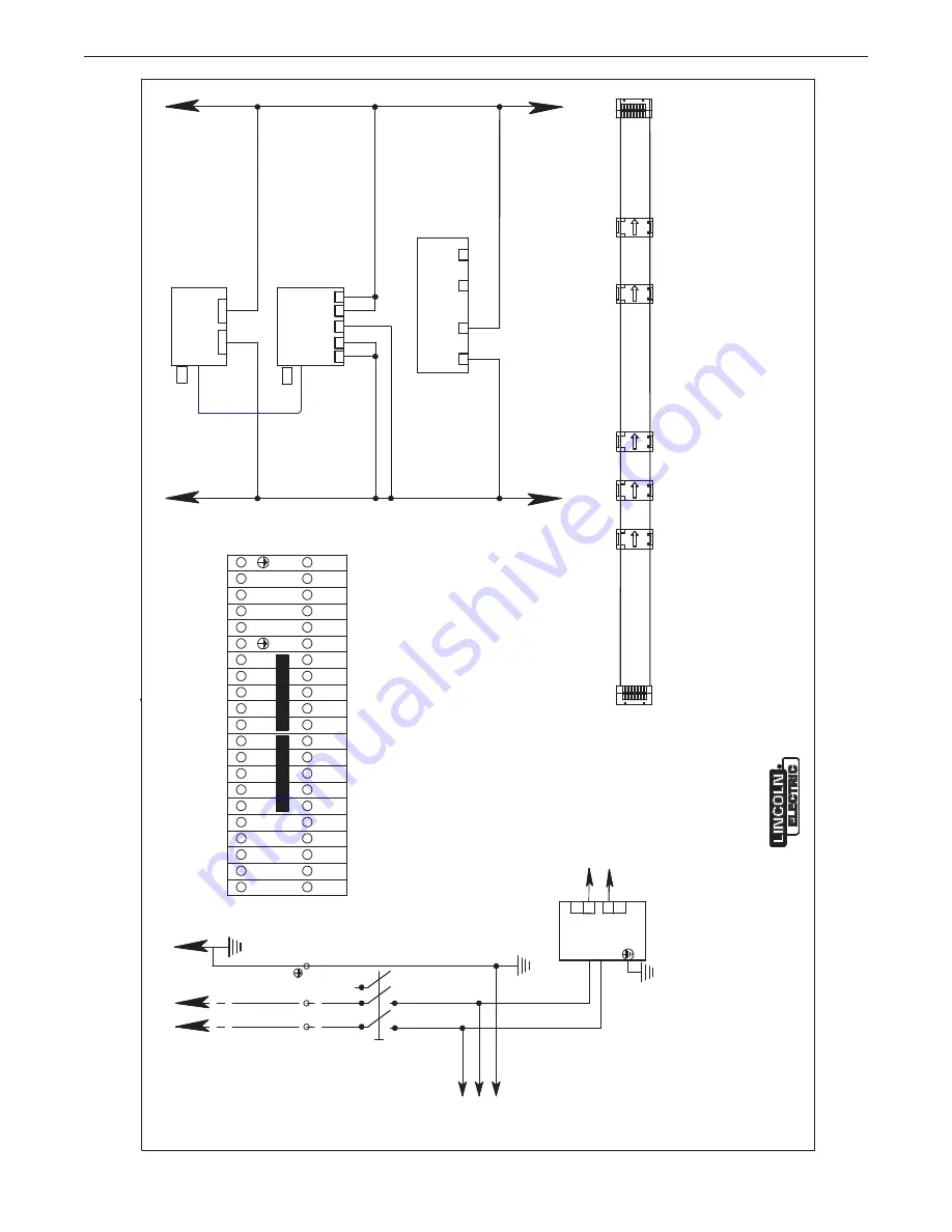
DIAGRAMS

F-1

Sa

le

an

Se

rv

ic

e t

hr

ou

gh

 S

ub

si

di

ar

ie

and

 D

is

tri

bu

to

rs

 W

or

ld

wi

de

C

le

ve

lan

d, 

O

hi

44

11

7-

11

99

  U

.S

.A

.

THE

 L

INCOLN

 ELEC

TR

IC

 CO

M

PAN

Y

W

or

ld

's

 L

ea

de

r i

W

el

di

ng

 a

nd

 Cu

tti

ng

 P

rod

uc

ts

S31

228

-7

06

PR

IN

T

A.

12

N

O

TE

S:

N

.A

. D

O

TT

ED

 L

IN

IN

D

IC

AT

C

O

N

N

EC

TI

O

N

AR

O

U

TS

ID

TH

PA

N

EL

.

N

.B

. U

SE

 U

R

AT

ED

 18

AW

G

 300

M

IN

 105

°C

 C

O

PP

ER

 L

EA

D

U

NL

ES

SP

EC

IF

IE

D

.

N

.C

. D

IS

C

O

NN

EC

TI

N

G

 M

EA

N

AN

D

 B

R

ANC

H

 C

IR

CU

IT


  P

R

O

TE

C

TI

O

N

 S

H

ALL

 BE

 P

R

O

VI

D

ED

 B

TH

IN

ST

AL

LE

R

N

.D

. D

IS

C

O

NN

EC

TH

JU

M

PE

R

 F

O

R

 F

R

O

N

PA

N

EL

 F

AN

 S

TA

R

FU

N

C

TI

O

N

, R

ET

AI

N


  T

H

IS

 J

U

M

PE

R

 F

O

R

 R

EM

O

TE

 S

TA

R

O

PT

IO

N

S.

23

0VA

C

 / 

115

50-

60

H

1~

N

.E

.

-

+

27

S1

32

A-

3P

L1

L2

N

2

L

FU

SE

D

 D

IS

C

O

NN

EC

T

D

C

PO

W

ER

24

VD

C

  3

.7

5A

PS

1

-

+

T3

T2

L3

L

N

X1

1

3
5

T1

L

N

6

4

2

AL

AR

M

  R

ED

FA

N

RU

N

N

IN

G

G

R

EE

N

PO

W

ER

   O

N

W

H

IT

E

R

ESE

T

DR

IVE

 A

LA

R

M

BL

AC

K

ST

AR

/ S

TO

P

FA

N

G

R

EE

N

LT1

LT2

LT3

S3

S2

PL

C

 2

SW

D

4

R

IB

BO

N

 T

O

R

O

UN

D

M

O

D

U

LE

SM

AR

TW

IR

C

AB

LE

 C

O

N

N

EC

TIO

N

1L

1

1

N1N G

X1

1

27

3

45

6

27

27

27

2

2

2

2

L

N

1N

1

1L

1

27

2

27

SMART RELAY PLC DISPLAY EASY819-DC-RC

27

24

 C

O

M

24

 V

D

C

27

2

2

 P

LC

27

24

V

0V

2

2

TR

1,

2

N

ET

W

O

R

K

TE

R

M

IN

AT

IO

N

R

ES

IS

TO

R

PL

C

1

PL

C

2

SW

D

4

SM

AR

W

IR

R

IB

BO

N

 T

O

 R

O

U

N

D

 M

O

D

U

LE

N

E

T1

N

E

T2

TR

1

D

C

-in

X2

24

V

0V

D

C

-O

U

T

X3

+2

4+

24

24

C

24

C

AU

X

AU

X

POW

POW

C

O

N

TR

O

R

EL

AY

EASY806-DC-SWD

N

E

T2

N

E

T1

TR

2

ETH

ER

N

ET

PA

TCH

 C

AB

LE

I1

N

.D

.

PRISM

®

Содержание Prism 4

Страница 1: ... L17587 19 L17587 20 L17587 21 L17587 22 L17587 23 L17587 24 L17587 25 L17587 26 L17587 27 L17587 28 L17587 29 L17587 30 L17587 31 L17587 32 L17587 33 L17587 34 L17587 35 L17587 36 L17587 37 Save for future reference Date Purchased Code ex 10859 Serial ex U1060512345 Operator s Manual Need Help Call 1 888 935 3877 to talk to a Service Representative Hours of Operation 8 00 AM to 6 00 PM ET Mon thr...

Страница 2: ...N A LARGE ROOM OR OUTDOORS natural ventilation may be adequate if you keep your head out of the fumes See below USE NATURAL DRAFTS or fans to keep the fumes away from your face If you develop unusual symptoms see your supervisor Perhaps the welding atmosphere and ventilation system should be checked WEAR CORRECT EYE EAR BODY PROTECTION PROTECT your eyes and face with welding helmet properly fitted...

Страница 3: ...ot engine parts and igniting Do not spill fuel when filling tank If fuel is spilled wipe it up and do not start engine until fumes have been eliminated 1 d Keep all equipment safety guards covers and devices in position and in good repair Keep hands hair clothing and tools away from V belts gears fans and all other moving parts when starting operating or repairing equipment 1 e In some cases it ma...

Страница 4: ...rm to ANSI Z87 I standards 4 b Use suitable clothing made from durable flame resistant material to protect your skin and that of your helpers from the arc rays 4 c Protect other nearby personnel with suitable non flammable screening and or warn them not to watch the arc nor expose themselves to the arc rays or to hot spatter or metal FUMES AND GASES CAN BE DANGEROUS 5 a Welding may produce fumes a...

Страница 5: ...ent passing through lifting chains crane cables or other alternate circuits This can create fire hazards or overheat lifting chains or cables until they fail 6 h Also see item 1 c 6 I Read and follow NFPA 51B Standard for Fire Prevention During Welding Cutting and Other Hot Work available from NFPA 1 Batterymarch Park PO box 9101 Quincy MA 022690 9101 6 j Do not use a welding power source for pipe...

Страница 6: ... fume at or near the arc and filter contaminants out of the air The ventilation or exhaust needed for your application depends upon many factors such as Workspace volume Workspace configuration Number of welders Welding process and current Consumables used mild steel hardfacing stainless etc Allowable levels TLV PEL etc Material welded including paint or plating Natural airflow Your work area has ...

Страница 7: ... org Supplemental Information Not listed Nuisance value maximum is 10 milligrams per cubic meter PEL value for iron oxide is 10 milligrams per cubic meter TLV value for iron oxide is 5 milligrams per cubic meter As respirable dust Subject to the reporting requirements of Sections 311 312 and 313 of the Emergency Planning and Community Right to Know Act of 1986 and of 40CFR 370 and 372 b The PEL fo...

Страница 8: ...REPLACEMENT FILTER OPTIONS C 1 THERMAL SUPPRESSION OPTION C 2 SYSTEM OVERVIEW C 2 INSTALLATION C 3 OPERATION AND DIAGNOSTICS C 5 DISCHARGE AND RECOVERY C 5 ALARM IDENTIFICATION AND TROUBLESHOOTING C 6 MAINTENANCE SECTION D MALFUNCTIONS AND EMERGENCIES EFFECTING THE FILTER UNIT D 1 ESCAPE OF NOXIOUS SUBSTANCES OR RADIATION D 1 PERIODIC MAINTENANCE D 2 MAINTENANCE SCHEDULE D 2 REPLACING FILTER CARTR...

Страница 9: ...SM CLEANING CONTROLS INPUT VOLTAGE NOMINAL 10 115 230V 1 50 60 Hz MAXIMUM CURRENT 1 6 A MAX ALARM LEVEL 1500Pa factory default A 1 TECHNICAL SPECIFICATIONS 24 BANK 2 DEEP X 3 WIDE L17587 9 32 BANK 2 DEEP X 4 WIDE L17587 29 40 BANK 2 DEEP X 5 WIDE L17587 30 48 BANK 2 DEEP X 6 WIDE L17587 31 56 BANK 2 DEEP X 7 WIDE L17587 11 64 BANK 2 DEEP X 8 WIDE L17587 32 72 BANK 2 DEEP X 9 WIDE L17587 33 MAXIMUM...

Страница 10: ...remote 6 Silencer top mount or remote 7 Silencer bracket top mount only varies by application 8 VFD Panel CUSTOMER SUPPLIED ITEMS see wire diagrams for details 9 Cable Remote Cleaning Panel to VFD Panel 10 VFD Motor Cable VFD Panel to Fan Motor 11 Power cables to cleaning panels and VFD panel NOTE L Series units with thermal suppression have additional components supplied with the L series unit th...

Страница 11: ...ration The installer is responsible for following federal state and local safety codes and regulations Before drilling verify locations of existing gas water or electrical conduits Excluded Uses Welding fumes containing oil Aluminum dust Burning or incandescent materials Cigarettes Aggressive media Water and moisture Explosive gases and or dust mixtures Dusts with toxic characteristics other than ...

Страница 12: ...7587 30 L17587 31 L17587 32 L17587 33 ONLY Step 1 Unpack the leg base w hopper Unpack leg base w hopper assembly and place it in desired location FIGURE A 1 STEP 2 PREPARE MAIN BODY FOR INSTALLATION ON TO LEG BASE FIGURE A 2 STEP 3 INSTALL MAIN MODULE ON LEG BASE HOPPER Apply strip foam gasket supplied in hopper carton completely around top of hopper flanges as shown Apply gasket on both sides of ...

Страница 13: ... module on leg base FIGURE A 4 FIGURE A 5 Assembled unit unit ready for top mount fan installation Lift main module on top of leg base Level the leg base hopper assembly before installing main module After assembly anchor the support legs to floor using appropriate concrete anchors supplied by installing contractor Location for 3 8 flange bolts 2 per each leg Location for 1 4 flange bolts 5 locate...

Страница 14: ...encer to be supported on top of adjacent module Step 4b Remote Fan L17587 3 L17587 6 L17587 15 L17587 22 L17587 27 ONLY Connect return air clean air ductwork to top duct adapters then to remote fan fan silencer optional Install foam strip gasket around circumference of bolt pattern both sides of bolt pattern then apply liquid sealant between foam strips Install foam strip gasket around circumferen...

Страница 15: ...silencer support bracket to top of module before installing silencer self tapping screws recommended Note support brackets for 4 bank units use roof panel fasteners and hang over edge of unit Outdoor applications venting filtered air outside require duct downturn on silencer outlet not supplied FIGURE A 7 Silencer support bracket Apply strip foam on both sides of bolt pattern and overlap in corner...

Страница 16: ...the dust collector b Insert Pitot tube and secure it with sheet metal screws not shown c Install Differential Pressure Sensor next to the Pitot tube See Figure A 10 FIGURE A 10 d Secure Differential Pressure Sensor using 3 sheet metal screws e Connect the clear tube from Pitot tube to the ve connection nipple right side of the sensor f Connect pressure sensor s wire to VFD as detailed in the VFD s...

Страница 17: ...URE A 13 c Install new filters making sure the first filter is pushed fully against rear of unit All remaining filters in each row push against the previous filter flange FIGURE A 14 d Reclasp filter handles FIGURE A 15 WARNING Connect green wire from control module above compressed air tank to this fitting Low Side Pressure Tap connect black tube from clean air side upper fitting on side of unit ...

Страница 18: ...IGURE A 16 LEFT TYPICAL SHIPPING CONFIGURATION RIGHT Rear inlet side of unit Door side of unit NOTE Do not apply liquid sealant at this time Leg base with controls to be placed on left when facing door side of unit Leg base s without controls to be placed to right of leg base with controls Filter removal tool on far right side l17587 2 l17587 6 l17587 9 only Location for 3 8 bolts 2 per leg Strip ...

Страница 19: ...om cross braces on facing sides then use the removed bolts to fasten through both legs and a cross brace to tie them all together L17587 9 CONFIGURATION SHOWN Join leg bases together by first removing bolts nuts from cross braces on facing sides Leg base sections are then joined by bolting through cross braces and both legs with previously removed bolts nuts For improved assembly bolt alignment fl...

Страница 20: ...PREPARE TO ASSEMBLE UPPER MOD ULES TOGETHER Apply strip foam gasket completely around all joining surfaces Apply gasket on both sides of holes and overlap in corners APPLY GASKET TO ALL SURFACES JOINING TO ADJACENT MODULE PRISM ...

Страница 21: ... in preparation for joining together STEP 15 PREPARE TO ASSEMBLE UPPER MOD ULES TOGETHER Apply bead of caulk between all double strips of foam then quickly proceed to step 16 Remove screws from top panels and slide them to the right as shown Remove screws from top panels and slide them to the left as shown PRISM ...

Страница 22: ...nation matches up two clearance holes Use the 2nd combination that matches a clearance hole to a tapping hole Drive the screw through the clearance hole identified by a silver outline Note Some fasteners will drive from one side of the unit and some from the other side Double set of holes Join upper clean air sections together through top which is made accessible by sliding top panels to side as s...

Страница 23: ...RS 3 8 THREAD FORMING Drive appropriate screws though clearance holes which are identified by a silver outline The thread forming screws will thread into an appro priately sized hole on the adjoining module B 2 B 2 B 2 B 2 B 2 B 2 B 2 A 11 A 4 A 4 A 4 B 2 A 11 A 6 A 6 A 6 A 6 A 6 A 6 A 4 A 10 A 10 PRISM ...

Страница 24: ... between double foam strips and fasten top panels in place using thread forming screws at all locations Access to fasten upper section together After modules are completely fastened together verify top gaskets are in good shape replace as needed then apply caulk between double foam strips and fasten top panels in place using thread forming screws at all locations PRISM ...

Страница 25: ...ect two modules together with the supplied 1m 40 long green cable Repeat on rear side modules Secure cables in same manner as done on other pre wired modules Connect air line between tanks as done on other pre assembled modules Repeat at rear side tanks PRISM ...

Страница 26: ...d sealant between all double strip foam gaskets then quickly proceed to lifting upper modules on to leg bases Level the leg base assembly before installing upper modules After assembly anchor the support legs to floor using appropriate concrete anchors supplied by installing contractor PRISM ...

Страница 27: ... each leg These should all be started before setting full weight of upper modules on leg bases Complete assembly by installing all flange bolts and then fully tighten 3 8 flange bolts Fully tighten all leg cross brace bolts Fasteners required 3 8 flange bolts 2 for each leg flange bolts 5 between each leg A 19 INSTALLATION Location for 3 8 flange bolts 2 per each leg Location for 1 4 flange bolts ...

Страница 28: ...LLATION STEP 21 COMPETING INSTALLATION Connect exhaust air clean air ductwork to top duct adapters then to remote fan fan silencer optional Connect supply air dirty air ductwork to rear inlet duct adapters PRISM ...

Страница 29: ...ollector b Insert Pitot tube and secure it with sheet metal screws not shown c Install Differential Pressure Sensor next to the Pitot tube See Figure A 10 FIGURE A 10 d Secure Differential Pressure Sensor using 3 sheet metal screws e Connect the clear tube from Pitot tube to the ve connection nipple right side of the sensor f Connect pressure sensor s wire to VFD as detailed in the VFD s wiring di...

Страница 30: ...ed fully against rear of unit All remaining filters in each row push against the previous filter flange FIGURE A 14 WARNING Connect green wire from control module above compressed air tank to this fitting Low Side Pressure Tap connect black tube from clean air side upper fitting on side of unit High Side Pressure Tap connect black tube from dirty air side lower fitting on side of unit Power feed f...

Страница 31: ...A 23 INSTALLATION d Reclasp filter handles FIGURE A 15 PRISM ...

Страница 32: ...ufacturer accepts no liability for any damages or injury resulting from such use The product has been built in accordance with state of the art standards and recognized safety regulations Only use this product when in technical perfect condition in accordance with its intended use and the instructions explained in the user manual MODIFICATIONS Modifications of parts of the product is not allowed R...

Страница 33: ... E Start Stop fan Switch F Main Switch Input Power NOTE REFERENCE CONTROL PANEL LABEL FOR WIRING SPECIFI CATIONS NOTE LAND POWER GROUND WIRE SHOULD BE LONGER THAN ALL OTHER WIRES Display System Control Panel FIGURE B 2 Functions A POWER Light white indicates the unit has power is online and available for operation Blinking light indicates that filter cleaning is in progress B ALARM Light red indic...

Страница 34: ...the filter pressure falls below the set point The VFD alarm can be reset by pushing the reset alarm button The filter change alarm only stops once the pressure across the filter is below the alarm set point A reset signal is sent to the VFD If it does not clear the alarm you must investigate the issue at the VFD enclosure with a qualified person able to view the LCD screen and trouble shoot the dr...

Страница 35: ...hree phase line voltage connection for optimal performance The VFD and Motor will be rated for the applied line voltage to the unit Ensure supply lines to the unit are properly fused and all local electrical codes are followed Pneumatics Check that the compressed air is connected Compressed air should be clean dry and oil free and at a maximum pressure of 87 psi 6 bar SET POINTS Default values ena...

Страница 36: ...ion KP4519 2 MERV 16 rated high efficiency filter cartridge featuring nano fibers KP4519 3 MERV 16 rated high efficiency filter cartridge featuring a thermal bonded PTFE membrane All filters should be replaced at the same time all should be of the same type Replacement filters include dust mask gloves and plastic bag for spent filter PRISM ...

Страница 37: ...t through the nozzles into the protected volume When the system s smoke detector is activated or the detection tubing is ruptured the integrated controls quickly shut down the fan and close the two dampers to create a protected volume A LED strobe light provides visual notification of any system discharge The stack light also gives visual feedback on any system malfunction as detailed in the Opera...

Страница 38: ...t as shown The following units have two inlet dampers one at each inlet plenum L17587 15 L17587 16 L17587 17 L17587 18 L17587 27 L17587 28 L17587 35 NOTE FOR UNITS WITH TOP MOUNTED FANS SKIP TO STEP 7 ON THESE UNITS THE EXHAUST DAMPER IS PRE INSTALLED UNDER THE FAN STEP 6 Install exhaust air damper near the outlet adapter on top of the unit as shown The following units require two exhaust dampers ...

Страница 39: ...rmination module attached to the 2DD module STEP 14 remote fan units only Connect Lincoln Smart Connect 4DD module above unit s rear compressed air tank to exhaust damper s 2DD module on top of unit using a 3m 10 ft long green cable If unit has a 2nd exhaust damper connect 1st damper s 2DD module to 2nd damper s 2DD module using a 3m 10ft long green cable STEP 15 remote fan units only Connect last...

Страница 40: ...ack light To allow continued system operation two of the alarms can be temporarily bypassed using the key switch box the smoke detector alarm and low pressure in the detection tubing circuit Note the important caution statements listed in the troubleshooting section Damper alarms can not be bypassed since they must be open for the fan to move air through the unit The discharge alarm can not be byp...

Страница 41: ...s with 3 seconds delay Smoke Alarm Smoke particulate detected in fan exhaust 3 Lower Light Three flashes with 3 seconds delay Intake Damper s Alarm After fan is started intake damper s fails to open within 10 seconds 4 Lower Light Four flashes with 3 seconds delay Exhaust Damper s Alarm After fan is started exhaust damper s fails to open within 10 seconds Upper High Intensity Light Continuous Flas...

Страница 42: ...mporarily Bypass 1 Turn keyed switch to Bypass 2 Hit reset on main control panel CAUTION Resolve cause of alarm as soon as possible to maintain early detection feature provided by the smoke alarm 3 To return to normal operation turn keyed switch back to Enable and then press reset on the main control panel Intake Damper s Alarm 1 After fan is started intake damper s fails to open in 10 seconds Dam...

Страница 43: ... accordance with statutory instructions using the plastic sack disposal system supplied Maintenance should only be performed by authorized qualified and trained persons skilled using appropriate work practices When cleaning equipment or replacing filter use personal protection equipment PPE such as gloves respirators and protective clothing to protect against overexposure to particulate It is reco...

Страница 44: ...ssure EVERY 6 MONTHS Ensure that the Cubic Feet per Minute CFM is operating to the engineered specifications based on the individual system UNIT HOUSING Clean housing with a non aggressive detergent Check the connections to the duct work seal if necessary Inspect and clean with a non aggressive detergent the filter control box YEARLY Inspect unit for proper operation and function address any issue...

Страница 45: ... filter has collected certain types of particulate which local agencies define as hazardous waste filter may be classified as hazardous waste and will need to be disposed in accordance with federal state and local regulations which could vary from state to state and between local municipalities within the state Use protective gloves If not carried out with the necessary caution may cause serious p...

Страница 46: ...pushed against rear of unit 2 Reclasp filter handles to lift filters to their sealed position 3 Re lock door handle using the supplied hex wrench or any standard 5 16 hex wrench 1 Slide filters out of unit through the door opening as shown See special note on next page for filter removal on units with 4 filters deep 2 If required by federal state and or local regulations and guidelines conceal fil...

Страница 47: ...7 31 L17587 32 L17587 33 L17587 34 L17587 35 units only Install 4 filters on each rail system pushing them fully against the rear of the unit D 5 MAINTENANCE For replacement use filter hook to pull rear two filters out of unit Engage tool hook into filter s flange recess to pull filter out of unit PRISM ...

Страница 48: ...bout specific adjustments maintenance or repair jobs which are not dealt with in this manual please contact Lincoln Electric Automation Department 888 935 3878 Make sure you have the following data on hand product name serial number purchase order number date for warranty verification If for any reason you do not understand the test procedures or are unable to perform the tests repairs safely cont...

Страница 49: ...on the Eaton Smartwire I O pack are illuminated on solid green is good flashing means the IO pack has power but is not recognized by the system Find the learn smartwire function reference in the manual During a cleaning an output LED flashes on for the I O pack it sends a 24VDC pulse to the air valve Check the cable connection from the valve to the I O pack to confirm a working valve or I O port s...

Страница 50: ...operly The air flow is diminished 1 Filter may be clogged 1 Replace filter if necessary 2 Make sure your duct pressure sensor is giving a proper reading into the VFD Fan speed is controlled via this input feeding into a PID control loop 3 If all recommended possible areas of misadjustment have been checked and the problem persists Contact your local Lincoln Authorized Field Service Facility 1 888 ...

Страница 51: ...arm light is on solid if controls know there is a fault with the VFD 2 Red alarm light is flashing if the DP alarm set point is reached 1 Press alarm reset and investigate VFD fault issue Note the VFD has an LCD display that will assist troubleshooting with a message or fault code to help determine reason for the fault 2 If the Differential Pressure read by the sensor is higher than your DP Alarm ...

Страница 52: ... JUMPER FOR REMOTE START OPTIONS 230VAC 115V 50 60Hz 1 N E 27 S1 32A 3P L1 L2 N 2 L FUSED DISCONNECT DC POWER 24VDC 3 75A PS1 T3 T2 L3 L N X1 1 3 5 T1 L N 6 4 2 ALARM RED FAN RUNNING GREEN POWER ON WHITE RESET DRIVE ALARM BLACK START STOP FAN GREEN LT1 LT2 LT3 S3 S2 PLC 2 SWD4 RIBBON TO ROUND MODULE SMARTWIRE CABLE CONNECTION 1L1 1 N 1N G X1 1 27 3 4 5 6 27 2727 2 2 2 2 L N 1N1 1L1 27 2 27 SMART R...

Страница 53: ...g and Cutting Products S31228 706PRINT A 12 2 3 4 5 6 7 9 10 11 12 27 13 27 14 1 INPUT 1 INPUT 2 INPUT 3 INPUT 4 INPUT 5 INPUT 6 INPUT 7 INPUT 8 INPUT 9 INPUT 10 INPUT 11 INPUT 12 OUTPUT 1 OUTPUT 2 OUTPUT 3 OUTPUT 4 OUTPUT 5 OUTPUT 6 3 2 4 5 6 7 8 9 10 11 12 START PLC1 INPUT PLC OUTPUT STOP RESET 18 DI 19 DI 27 DI 12 24VDC VFD 1 4 5 3 VFD ALARM 04 06 RELAY 2 PRISM ...

Страница 54: ...RATION UNSUCCESSFUL N B DRY CONTACT BETWEEN 1 2 IS UNIT REMOTE START UNIT WILL OUTPUT A HIGH 24VDC ON 4 REFERENCED TO 3 IF UNIT IS ON AND RUNNING ACTIVE FUME EXTRACTION N C PRESSURE SENSOR JUMPERS SHALL BE CONFIGURED AS SHOWN N D ITEM 8 SHALL BE CUT AT FEMALE END AND CONNECT TO THE ROBOT I O AS SHOWN N E CUT TO LENGTH BASED ON FIELD WIRING N F USE ITEM 8 OR ITEM 5 FACTORY DEFAULT OR SIMILAR CABLE ...

Страница 55: ...idiaries and Distributors Worldwide Cleveland Ohio 44117 1199 U S A S31228 761PRINT A 15 TANK TANK 6 7 12 11 9 10 6 N H 4 BANK TANK 6 7 11 9 10 N H TANK TANK TANK 6 6 7 12 12 11 10 6 9 N H 12 BANK 8 BANK SPLITTER PIN COLOR FUNCTION 2 WHITE WH O0 O1 3 BLUE BL 0V GND VALVE WIRING 5 5 5 16 15 14 13 16 15 14 13 17 18 19 20 24 23 22 21 20 19 18 17 16 15 14 13 1 1 2 2 1 1 1 1 2 2 2 2 1 2 2 1 2 2 2 2 1 1...

Страница 56: ...GE 1 CONTROL OPT ION 4 GR N E 8 N B ITEM 19 QUANTITY IS 2 FOR THIS OPTION 19 N C R OBOT 1 CONTR OLL E R FAN START STOP FE E DBAC K INDICA TION OUTPUT INPUT INDICATION SOLID ON RUNN ING BLINKING FAULT OR FILTER CH ANGE TURN ON CONTINUOUSLY TO RU N FAN BLACK BLUE BROWN WHITE FAN S TART S TOP FEE D BACK INDICATION R OB OT 1 R OBOT 2 CONTR OLL E R OUTPUT INPUT INDICATION SOLID ON RUNN ING BLINKING FAU...

Страница 57: ...D SETUP INSTRUCTIONS ARE ON SHEET2 OF THE DUAL OVERLOAD ASSEMBLIES OVERLOAD TRIP SIGNAL MUST BE CONFIGURED IN VFD AFTER WIRING IT CONTROL PANEL SMARTWIRE VFD KIT SIGNAL X1 1 X2 06 START X1 3 X2 03 24VDC X1 4 X2 05 STOP X1 5 X2 04 RESET X1 27 X2 10 DCV ALARM COM X1 6 X2 11 ALARM NC VFD WIRING JUMPER WIRE ON VFD KIT X2 03 X2 05 SEE PAGE 4 FOR REMOTE CONTROL OPTIONS SEE PAGE 2 PAGE 3 FOR BANK OPTIONS...

Страница 58: ... 12 18 19 20 14 15 16 13 17 1 2 2 1 1 2 2 1 1 2 2 1 1 2 2 1 1 2 2 1 FROM PAGE 1 20 BANK 12 6 6 12 12 11 9 10 6 7 TANK TANK TANK 1 2 3 4 5 6 7 8 9 10 11 12 22 23 24 18 19 20 14 15 16 13 17 21 1 2 1 2 1 2 1 2 1 2 1 2 2 1 2 1 2 1 2 1 2 1 2 1 26 FROM PAGE 1 24 BANK N K 12 12 T T T T A A A A N N N N K K K K T T T T A A A A N N N N K K K K T T T T A A A A N N N N K K K K 6 6 6 6 6 TANK TANK TANK 6 12 11...

Страница 59: ...NK 24 23 22 21 1 2 2 1 TANK 1 2 2 1 TANK 1 2 2 1 TANK 12 11 10 9 1 2 2 1 TANK 1 2 2 1 TANK 4 3 2 1 1 2 2 1 TANK 1 2 2 1 TANK 1 2 2 1 TANK 1 2 2 1 TANK 1 2 2 1 TANK 1 2 2 1 TANK 1 2 2 1 TANK 8 7 6 5 16 15 14 13 20 19 18 17 1 2 2 1 TANK 1 2 2 1 TANK 28 27 26 25 36 35 34 33 72 71 70 69 68 67 66 65 64 63 62 61 60 59 58 57 56 55 54 53 52 51 50 49 48 47 46 45 44 43 42 41 40 39 38 37 1 2 2 1 TANK 40 BANK...

Страница 60: ... E 18 N B ITEM 19 QUANTITY IS 2 FOR THIS OPTION 19 N C N C N C N C N C GR N E 18 N B ROBOT 1 CONTROL LER FAN START STOP FE EDBACK INDICATION OUTPUT INPUT INDICATION SOLID ON RUNN ING BLINKING FAULT OR FILTER CH ANGE TU RN ON CONTIN UOUSLY TO RUN FAN BLACK BLUE BROWN WHITE FAN STA R T STOP FEED BACK INDICATION ROBOT 1 N C ITEM 18 CON NECTS TO ITEM 4 IN PAGE 1 N H ROBOT 1 CONTROL LER FAN START STOP ...

Страница 61: ... ROBOTIC START STOP SIMULATOR 1 17 BYPASS RESET CONTROL 1 18 DUAL PRESSURE SWITCH ASSEMBLY 1 19 CONNECTOR 5 PIN MALE STRAIGHT 5 20 SMOKE DETECTOR WIRED 1 21 DAMPER ACTUATOR ELECTRONIC 2 22 RED STROBE MODULE 1 23 RED CONTINUOUS LIGHT MODULE 1 24 STACK LIGHT MOUNTING BASE 1 25 M12 WIRING RECEPTACLE 1 26 AUXILIARY SWITCH SPDT 2 27 ROBOT INTERFACE ISOLATION RELAY KIT 28 IF15 1 29 PROGRAMMABLE TIMER CO...

Страница 62: ...4 I O Ch1 0 GREEN GN 5 N C N C ITEM 18 SMARTWIRE CABLE CONNECTOR SPLITTER PIN COLOR FUNCTION 2 WHITE WH O0 O1 3 BLUE BL 0V GND ITEM 9 VALVE WIRING NOTES N A DURING INSTALLATION ANY SMARTWIRE COMPONENT REPLACEMENT PRESS AND HOLD LEARN PUSH BUTTON FOR AT LEAST 2 SECONDS TO INITIATE SMARTWIRE LEARN SOLID GREEN LED LIGHTS INDICATES SUCCESSFUL REGISTRATION OF MODULES BLINKING GREEN LEDS ON MODULES INDI...

Страница 63: ...N CONTROL OPTION 4 GY 7 N B N D ITEM 27 QUANTITY IS 2 FOR THIS OPTION 27 N C N C N C N C N C GY 7 N B N D ROBOT 1 CONTROLLER FAN START STOP FEEDBACK INDICATION OUTPUT INPUT INDICATION SOLID ON RUNNING BLINKING FAULT OR FILTER CHANGE TURN ON CONTINUOUSLY TO RUN FAN BLACK BLUE BROWN WHITE FAN START STOP FEED BACK INDICATION ROBOT 1 N C ITEM 7 CONNECTS TO ITEM 6 IN PAGE 1 FB CR2 3 4 2 1 A1 5 A2 RUN C...

Страница 64: ...L SMARTWIRE VFD KIT SIGNAL X1 1 X2 06 START X1 3 X2 03 24VDC X1 4 X2 05 STOP X1 5 X2 04 RESET X1 27 X2 10 DCV ALARM COM X1 6 X2 11 ALARM NC VFD WIRING JUMPER WIRE ON VFD KIT X2 03 X2 05 SEE PAGE 3 FOR REMOTE CONTROL OPTIONS CONNECTION 9 SEE TABLE DETAIL E 12 ITEM DESCRIPTION QTY 1 CONTROL PANEL 8 B W THERMAL SUPP 1 2 SENSOR PANEL 1 3 CABLE ASSEMBLY 2FT 1 4 SMART WIRE DT I O 2X DIGITAL 3 5 SMART WI...

Страница 65: ...2 I O Ch2 1 WHITE WH 3 0V GND N C 4 I O Ch1 0 GREEN GN 5 N C N C ITEM 18 SMARTWIRE CABLE CONNECTOR SPLITTER PIN COLOR FUNCTION 2 WHITE WH O0 O1 3 BLUE BL 0V GND ITEM 9 VALVE WIRING 2 2 1 1 18 19 19 19 21 11 19 19 DUAL PRESSURE SWITCH ASSEMBLY ITEM 18 DUAL PRESSURE SWITCH ASSEMBLY CONNECTIONS 4 4 6 4 6 PIN DETAILS 26 TANK 5 6 10 8 2 2 1 1 34 35 33 35 32 N H NOTES N A DURING INSTALLATION ANY SMARTWI...

Страница 66: ...THIS OPTION CONTROL OPTION 4 GY 7 N B N D ITEM 27 QUANTITY IS 2 FOR THIS OPTION 27 N C N C N C N C N C GY 7 N B N D ROBOT 1 CONTROLLER FAN START STOP FEEDBACK INDICATION OUTPUT INPUT INDICATION SOLID ON RUNNING BLINKING FAULT OR FILTER CHANGE TURN ON CONTINUOUSLY TO RUN FAN BLACK BLUE BROWN WHITE FAN START STOP FEED BACK INDICATION ROBOT 1 N C ITEM 7 CONNECTS TO ITEM 6 IN PAGE 1 FB CR2 3 4 2 1 A1 ...

Страница 67: ...X DIGITAL 5 SMART WIRE DT I O 4X DIGITAL 6 SMART WIRE SPLIT DEVICE 10 11 7 CABLE ASSEMBLY 20M 3 4 8 24VDC SOLENOID 9 CABLE ASSEMBLY 1 5M 10 CABLE ASSEMBLY SINGLE END 11 DT BUS TERMINATION MODULE 12 CABLE ASSEMBLY SINGLE END 1 2 13 CABLE 9C 14 CABLE 3C SHIELD 15 PRESSURE TRANSMITTER 16 ROBOTIC START STOP SIMULATOR 17 BYPASS RESET CONTROL 18 DUAL PRESSURE SWITCH ASSEMBLY 19 CONNECTOR 5 PIN MALE STRA...

Страница 68: ...O SWITCH TRIPS WHEN DAMPER IS FULLY OPEN EXPECTED AN OPEN SIGNAL WHEN RUN THE FAN SET MOTOR ROTATION SWITCH TO 0 FOR EXHAUST N E CONNECTION 10 SEE TABLE CONNECTION 11 SEE TABLE EXHAUST DAMPER RECTANGULAR DUAL FAN ONLY 2 1 19 19 21 4 6 26 CONNECTION CONTINUED SEE NEXT PAGE BELIMO SWITCH PIN COLOR FUNCTION CABLE COLOR 1 BROWN BR 24V DC PURPLE 2 WHITE WH I O Ch2 1 RED RD 3 BLUE BL 0V GND N C 4 BLACK ...

Страница 69: ...ETWEEN 1 2 IS UNIT REMOTE START UNIT WILL OUTPUT A HIGH 24VDC ON 4 REFERENCED TO 3 IF UNIT IS ON AND READY FOR ACTIVE FUME EXTRACTION N C PRESSURE SENSOR JUMPERS SHALL BE CONFIGURED AS SHOWN N D ITEM 7 SHALL BE CUT AT FEMALE END AND CONNECT TO THE ROBOT I O AS SHOWN N E TRIM CABLE LENGTHS TO GIVE A LOOP FROM DAMPER TO IO MODULE COVER WITH BLACK SHEATH USED ON SMARTWIRE GREEN CABLES N F USE ITEM 7 ...

Страница 70: ...OR THIS OPTION CONTROL OPTION 4 GY 7 N B N D ITEM 27 QUANTITY IS 2 FOR THIS OPTION 27 N C N C N C N C N C GY 7 N B N D R OB OT 1 CONTR OLLE R FAN S TART STOP FE EDBAC K INDICA TION OUTPUT INPUT INDICATION SOLID ON RUNNING BLINKING FAULT OR FILTER CH ANGE TURN ON CONTINUOUSLY TO RUN FAN BLACK BLUE BROWN WHITE FAN STAR T STOP FEED BACK INDICATION ROB OT 1 N C ITEM 7 CO NNE CT S TO ITEM 6 IN PAGE 1 F...

Страница 71: ...R T R ALARM 1 HAVC ALARM 2 NC NC NC NC NC NC NO NO NO NO NO NO ALARM 2 HAVC ALARM 1 COM COM COM COM COM COM TROUBLE TROUBLE INPUT POWER 24 AC DC N 115H N 230H 460V 50Hz 60Hz 3 INDUCTION MOTOR 460V 50Hz 60Hz 3 INDUCTION MOTOR DUAL MOTOR WIRING DUAL THERMAL OVERLOAD JUNCTION BOX ASSEMBLY N K 32 DUAL MOTOR SMOKE DETECTORS D DETAIL D 12 12 6 1 2 20 20 N 115H 230H 24 AC DC N INPUT POWER TROUB LE TROUB ...

Страница 72: ...PER IS FULLY OPEN EXPECTED AN OPEN SIGNAL WHEN RUN THE FAN SET MOTOR ROTATION SWITCH TO 0 FOR EXHAUST N E CONNECTION 10 SEE TABLE CONNECTION 11 SEE TABLE 2 1 19 19 21 4 6 26 CONNECTION CONTINUED SEE NEXT PAGE BELIMO SWITCH PIN COLOR FUNCTION CABLE COLOR 1 BROWN BR 24V DC PURPLE 2 WHITE WH I O Ch2 1 RED RD 3 BLUE BL 0V GND N C 4 BLACK BK I O Ch1 0 N C 5 GRAY GY N C N C SMARTWIRE CABLE CONNECTOR DAM...

Страница 73: ...SFUL N B DRY CONTACT BETWEEN 1 2 IS UNIT REMOTE START UNIT WILL OUTPUT A HIGH 24VDC ON 4 REFERENCED TO 3 IF UNIT IS ON AND READY FOR ACTIVE FUME EXTRACTION N C PRESSURE SENSOR JUMPERS SHALL BE CONFIGURED AS SHOWN N D ITEM 7 SHALL BE CUT AT FEMALE END AND CONNECT TO THE ROBOT I O AS SHOWN N E TRIM CABLE LENGTHS TO GIVE A LOOP FROM DAMPER TO IO MODULE COVER WITH BLACK SHEATH USED ON SMARTWIRE GREEN ...

Страница 74: ...OPTION CONTROL OPTION 4 GY 7 N B N D ITEM 27 QUANTITY IS 2 FOR THIS OPTION 27 N C N C N C N C N C GY 7 N B N D ROBOT 1 CONTROLLER FAN START STOP FEEDBACK INDICATION OUTPUT INPUT INDICATION SOLID ON RUNNING BLINKING FAULT OR FILTER CHANGE TURN ON CONTINUOUSLY TO RUN FAN BLACK BLUE BROWN WHITE FAN START STOP FEED BACK INDICATION ROBOT 1 N C ITEM 7 CONNECTS TO ITEM 6 IN PAGE 1 FB CR2 3 4 2 1 A1 5 A2 ...

Страница 75: ... A A A U V W U V W M1 M2 T2 X2 03 12 X2 05 19 N C OVERLOAD MONITOR CABLE VFD TB X2 03 TERMINAL 12 24VDC TO OL1 TERMINAL 95 OL1 TERMINAL 96 TO OL2 TERMINAL 95 OL2 TERMINAL 96 TO VFD TB X2 05 DIGITAL INPUT TERMINAL 19 THERMAL OVERLOAD FRAME D TORQUE SPEC AUX CONTACT TERMINAL SCREW M3 5 TIGHTENING TORQUE NM 0 8 1 2 LB IN 7 10 6 MOTOR POWER TERMINAL SCREW M6 TIGHTENING TORQUE NM 3 5 LB IN 31 N E WIRE ...

Страница 76: ... 12 X2 05 19 N C OVERLOAD MONITOR CABLE VFD TB X2 03 TERMINAL 12 24VDC TO OL1 TERMINAL 95 OL1 TERMINAL 96 TO OL2 TERMINAL 95 OL2 TERMINAL 96 TO VFD TB X2 05 DIGITAL INPUT TERMINAL 19 THERMAL OVERLOAD FRAME C TORQUE SPEC AUX CONTACT TERMINAL SCREW M3 5 TIGHTENING TORQUE NM 0 8 1 2 LB IN 7 10 6 MOTOR POWER TERMINAL SCREW M4 TIGHTENING TORQUE NM 1 8 LB IN 16 WIRE SIZE TORQUE 10 350 300 KCMIL 31 1 N m...

Страница 77: ......

Страница 78: ...parts or electrode with skin or wet clothing l Insulate yourself from work and ground l No toque las partes o los electrodos bajo carga con la piel o ropa moja da l Aislese del trabajo y de la tierra l Ne laissez ni la peau ni des vête ments mouillés entrer en contact avec des pièces sous tension l Isolez vous du travail et de la terre l Berühren Sie keine stromführenden Teile oder Elektroden mit ...

Страница 79: ... und Entlüftung des Arbeitsplatzes l Mantenha seu rosto da fumaça l Use ventilação e exhaustão para remover fumo da zona respiratória l Turn power off before servicing l Desconectar el cable de ali mentación de poder de la máquina antes de iniciar cualquier servicio l Débranchez le courant avant l entre tien l Strom vor Wartungsarbeiten abschalten Netzstrom völlig öff nen Maschine anhalten l Não o...

Страница 80: ... advice once it has been given nor does the provision of information or advice create expand or alter any warranty with respect to the sale of our products Lincoln Electric is a responsive manufacturer but the selection and use of specific products sold by Lincoln Electric is solely within the control of and remains the sole responsibility of the customer Many variables beyond the control of Linco...

Отзывы: