Lincoln Electric CWT WOC-2 Скачать руководство пользователя страница 16


2.2  CABLES 

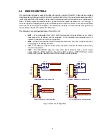
Connect a suitable source of 115-vac power to the power input connector using a power cable.  Refer 

to Appendix A for power cable connection information for the power cable assembly.  Connect the 

stepper motor drive cable (CWT P/N S3W5034) to the motor connector on the rear panel.  The 

maximum motor cable length is 75 ft.  Refer to Appendix A for motor control cable connection 

information.  Connect the operator pendant cable to the COMM connector on the rear panel.  


Warning

Do not connect or disconnect the stepper motor cable with power applied 

to the WOC-2 controller.


If the controller is being used with an external Master Modbus Controller in place of the operator hand 

pendant then connect the RS-485 cable to the RS-485 COMM connector on the rear panel.  Connect 

the other end of the cable to the Modbus Master RS-485 serial port. 

(Note: See section 4.0 for Modbus 

Communications Information) 
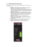
 

2.3  OPEARTION 

To operate the WOC-2 controller turn the power switch to the on position. The power switch should 

illuminate indicated ac power is supplied to the control. The three (3) lower LED’s should illuminate 

indicating the WOC-2 power supplies are operation. The “COMM” LED will pulse from green to red 

indicating communications between the pendant and the WOC-2 controller. When the WOC-2 controller 

is powered up the Stepper motor drive power is disabled. Before using the control functions the user 

must initialize the Slide. Before initializing the WOC-2 make sure that the oscillation slide is free to move.  


To initialize the slide assembly toggle the “

RUN

” switch on the pendant to the “

ON

” position. The “

DRIVE 

ON

” LED will eliminate indicating power has been applied to the motor and the Slide brake has been 

energized. If the Oscillation slide has limit switches the controller will move the slide in the CCW direction 

until the CCW limit is activated. The WOC-2 “

CCW LIMIT

” led will illuminate. The controller will move, 

at a slow speed in the CW direction until the CCW limit is deactivated and the “

CCW LIMIT

” led will be 

off. The slide is now in the “Home Position”. If the “

RUN

” switch is left on during the initialize sequence 

and if linear slide is used the slide will move to the center of the slide. Toggle the “

RUN

” switch to the 

OFF

” position. This sequence is only required when the WOC-2 controller is first powered up or if the 

remote INP2 is activated while the “

RUN

” switch is off.   


After the slide is initialized use the “JOG” switch to move the slide to the desired oscillation center 

position Use the “SPEED” control to set the desire oscillation and jog slide speed. Use the “WIDTH” 

control to set the oscillation width. Use the “LEFT” Dwell to set the left (CCW) position delay time. Use 

the “RIGHT DWELL” to set the right (CW) position oscillation delay time. To start the oscillation turn the 

“RUN” switch to the “ON” position. To jog the oscillation center position set the “JOG” switch to the “CW” 

or “CCW”. The Oscillation center position will be moved in desired direction.  If the JOG switch is held 

in the “CCW/CW” position the oscillation center position will updated every 0.1 seconds until the switch 

is released.  If the oscillation pattern reaches it maximum slide position the “JOG” function will be 

terminated in that direction. 


Note:

 The “RIGHT (CW)” and “LEFT (CCW)“ position refer to the slide motion 

when facing the front of the slide assembly. 


The WOC-2 controller uses a stepper motor drive system. The controller determines slide position by 

tracking the number of steps required to move to a specific location.   If the slide assembly cannot move 

due to some obstruction the stepper motor will enter a stall condition and the WOC-2 controller will lose 

its positional information. The WOC-2  and drive motor will not be damaged under this condition. 

However the WOC-2  controller should be powered cycled and reinitialized after clearing the stall 

condition. 


Содержание CWT WOC-2

Страница 1: ...ster Authorized Service and Distributor Locator www lincolnelectric com locator E8M5005 Issue Date Nov 20 Lincoln Global Inc All Rights Reserved For use with machines having Numbers E0A5025 E0A5026 Sa...

Страница 2: ......

Страница 3: ...A LARGE ROOM OR OUTDOORS natural ventilation may be adequate if you keep your head out of the fumes See below USE NATURAL DRAFTS or fans to keep the fumes away from your face If you develop unusual s...

Страница 4: ...hot engine parts and igniting Do not spill fuel when filling tank If fuel is spilled wipe it up and do not start engine until fumes have been eliminated 1 d Keep all equipment safety guards covers and...

Страница 5: ...m to ANSI Z87 I standards 4 b Use suitable clothing made from durable flame resistant material to protect your skin and that of your helpers from the arc rays 4 c Protect other nearby personnel with s...

Страница 6: ...nt passing through lifting chains crane cables or other alternate circuits This can create fire hazards or overheat lifting chains or cables until they fail 6 h Also see item 1 c 6 I Read and follow N...

Страница 7: ...ing used in the environment is compatible This may require additional protection measures h the time of day that welding or other activities are to be carried out The size of the surrounding area to b...

Страница 8: ...US MEMORY MAP 18 5 1 GENERAL DESCRIPTION 18 5 2 SUPPORTED MODBUS COMMANDS 18 5 3 MEMORY MAP FOR COILS MODBUS COMMAND 01 05 15 18 5 4 COIL DEFINITIONS AND OPERATION 19 5 5 MEMORY MAP FOR HOLDING REGIST...

Страница 9: ......

Страница 10: ...oscillator has a single 5 8 inch diameter output shaft for attachment of the user supplied welding torch The oscillator module can be installed in any position and with a maximum rotational displaceme...

Страница 11: ...outputs CR1 READY and CR2 OSC ON There are two Isolated inputs INP1 OSC ON and INP2 INITIALIZE can be used to remote activate the Oscillator and to reinitialize the slide The WOC can also be used as a...

Страница 12: ...esolution 10 micro steps step Velocity 10 8000 steps sec Note Max Speed Depends on Slide Assembly Acceleration 10 1000 steps sec Index Step Count 1 65535 steps Index Scale Factor 1 255 steps step scal...

Страница 13: ...rive motor it is controlling The maximum motor drive cable length is 75 ft Mount the WOC 2 controller in a location that allows easy access to the front and rear panel Figure 2 2 shows the WOC 2 Syste...

Страница 14: ...ntrol Enclosure FIG 2 2 WOC 2 Control Enclosure Mounting Dimensions 10 250 0 375 11 000 9 250 0 875 1 250 0 477 2 250 4X 0 281 4 750 MOTOR MAX 6 FOR CABLE CLEARANCE TOP VIEW SIDE VIEW FRONT VIEW REAR...

Страница 15: ...6 Figure 2 3 shows the dimensions for the Operator Pendant FIG 2 3 Operator Pendant Dimensions WOC 2 PENDANT 2 000 3 000 3 500 5 750 0 250 RUBBER FEET HANDLES 19 FT...

Страница 16: ...ion until the CCW limit is activated The WOC 2 CCW LIMIT led will illuminate The controller will move at a slow speed in the CW direction until the CCW limit is deactivated and the CCW LIMIT led will...

Страница 17: ...is only active when not jogging or oscillating the slide CR1 This READY output is active when the WOC controller is initialized and ready for normal operation CR2 This OSC RUN output is active when th...

Страница 18: ...ill be disabled CW LIMIT This LED indicates the status of the CW Right position limit switch in the mechanical slide assembly LED off indicates limit is not active LED on indicates the CW limit has be...

Страница 19: ...W position slide will be move in the CCW Left direction When the switch is set to the CW position the slide will be moved in the CW Right direction If for some reason the slide has been stalled or is...

Страница 20: ...SETUP If the WOC 2 controller is being used with a CWT slide or stepper motor no modification of the control parameters are required If the controller is being used with a different stepper motor the...

Страница 21: ...ignal rated at 0 5 amps The output will be set at 24 vdc for 0 5 seconds to allow full power pull in then the output will be PWM modulated at 2 0 khz to provide a 12 vdc output for reduced power brake...

Страница 22: ...FACE The WOC 2 is designed to use any 2 phase stepper motor with a current rating of 1 0 6 5 amps The following is an example of how to interface a 2 phase stepper motor to the WOC 2 controller FIG 3...

Страница 23: ...that indicates the current factory setting by AXIS DRIVE NUMBER The Mode of communications is determined by the setting of S1 Dip switch and the JP5 A B jumpers located on the Drive CPU P C Board FIG...

Страница 24: ...the following data format Baud Rate 19 200 Full Duplex Word Length 8 Data Bits One Stop and no parity Hand Shaking None 4 4 PORT PROTOCOL The Protocol consists of a command string and optional data b...

Страница 25: ...Active 7 Left Dwell Bit M2 Read Write Modbus Coils CR9 CR16 Inputs BIT Function 0 Enable Drive 1 Home Slide 2 Halt Move 3 Index CW 4 Index CCW 5 Enable Weave Mode 6 Save Default Configuration data in...

Страница 26: ...nds V5 Current Position MSB ISB2 V6 Current Position ISB1 LSB V7 Move Position MSB ISB2 V8 Move Position ISB1 LSB V9 Max Position MSB ISB2 V10 Max Position ISB2 LSB V11 Home Speed V12 MSB LSB MSB Mode...

Страница 27: ...il Status 0 31 03 Read Holding Registers 0 21 05 Force Single Coil 0 15 06 Preset Single Register 0 21 15 Force Multiple Coils 0 15 16 Preset Multiple Registers 0 21 17 Report Slave ID 5 bytes 5 3 Mem...

Страница 28: ...er definitions address 0 19 REGISTER ADDRESS DESCRIPTION 1 0 Motor Speed in steps msec 1 62535 2 1 Oscillation Width in Steps 1 65535 3 2 Right Dwell Time in 0 01 seconds 0 62535 4 3 Left Dwell Time i...

Страница 29: ...ction commands Refer to Section 4 5 for summary of the Register functions Under normal conditions do not write to Register 20 WARNING Changing this value may result in a catastrophic failure of the co...

Страница 30: ...ad 16 coils Command 0x01 address 0 starting at address 0 This loads the WOC 2 coils status 4 If the slide being used has a CCW limit then set Coil 10 address 9 using command 0x05 or 0x15 This will ena...

Страница 31: ...and Center positions based on the Width set in REG 2 and the current position of the slide To halt the oscillation clear COIL 14 Command 0x05 address 13 The oscillation will end when the slide has re...

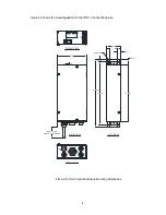
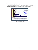
Страница 32: ...23 APPENDIX A SYSTEM DRAWINGS A 1 WOC 2 Enclosure Assembly 110VAC P N S3A5171...

Страница 33: ...Harness Comm 10 1 S5A5079 PCB Assembly MSC 2 11 1 S5A5092 PCB Assembly ATC III Interface 12 1 X3P5875 Connector Housing Plug 3 Circuit 13 1 X3S5078 Switch Rocker 14 1 X3T5095 Supply Power Ac DC 24VDC...

Страница 34: ...25 A 2 WOC 2 Enclosure Assembly 220VAC P N S3A5172...

Страница 35: ...Harness Comm 10 1 S5A5079 PCB Assembly MSC 2 11 1 S5A5092 PCB Assembly ATC III Interface 12 1 X3P5875 Connector Housing Plug 3 Circuit 13 1 X3S5090 Switch Rocker 14 1 X3T5095 Supply Power Ac DC 24VDC...

Страница 36: ...27 A 3 WOC 2 Operator Pendant P N E3A5069...

Страница 37: ...lack Self Adhesive 21 2 X6S5026 Spacer 4 40 x 1 Long Female Female 22 6 Screw 4 40 x 1 4 Pan Head w Inter Lock Washer 23 4 Screw 6 32 x 1 4 Pan Head w Inter Lock Washer 24 1 Nut Hex 6 32 25 1 Screw 6...

Страница 38: ...Step Cable P N S3W5034 ITEM QTY PART NO DESCRIPTION 1 1 X3P5596 Connector Plug 12 Circuit 2 1 X3P5586 Connector Plug 12 Circuit 3 1 X3P5589 Clamp Cable 4 2 X3P5505 Boot Cable Clamp 5 25 X3W0077 Cable...

Страница 39: ...able M12 8 Circuit Male Straight Single Ended 2 2 Sleeve Cable 3 9 Sleeve Wire Makers 4 1 Tubing Black Heat Shrink 3 8 Diameter 1 Long WIRE COLOR PIN NO REFERENCE WHITE 1 INP1 BROWN 2 INP2 GREEN 3 ICO...

Страница 40: ......

Страница 41: ...parts or electrode with skin or wet clothing l Insulate yourself from work and ground l No toque las partes o los electrodos bajo carga con la piel o ropa moja da l Aislese del trabajo y de la tierra...

Страница 42: ...d Entl ftung des Arbeitsplatzes l Mantenha seu rosto da fuma a l Use ventila o e exhaust o para remover fumo da zona respirat ria l Turn power off before servicing l Desconectar el cable de ali mentac...

Страница 43: ...tomer s particular purpose with respect to such information or advice As a matter of practical consideration we also cannot assume any responsibility for updating or correcting any such information or...

Отзывы: