3. Product Overview
RAP-B511 series
– User's Manual
15
3.1.1. Hidden Functions
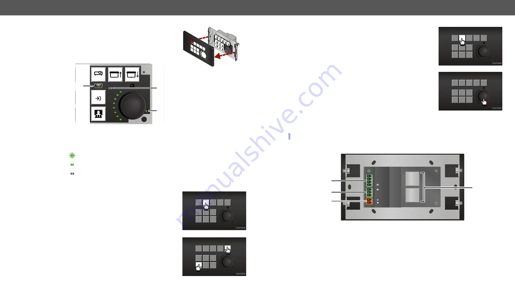
After removing the front plate (no special tool needed, just pull apart
by hands), a USB connector, a reset button, and a live led can be seen.
1
USB Port
USB mini-B connector can be used for LDC access or firmware upgrade.
2
Reset Button
Hidden button to restart the device.
3
Live LED
blinking The unit is powered and ready to use.
on
The device is powered, but the CPU is not running.
off
The unit is NOT powered or out of operation.
3.1.2. Special Functions
Set Dynamic IP Address (DHCP)
Step 1.
Keep the 2nd button pressed for
5 seconds;
all front panel LEDs
start to blink.
Step 2.
Release the button, then press it
3 times
quickly. DHCP is now
enabled.
Reset the Device
Step 1.
Keep the 5th and the 9th button pressed for
10 seconds
.
Step 2.
Release the buttons. The mute LED lights up when the device
restarts.
OFF
AUTO
3
2
1
Restore Factory Default Settings
Step 1.
Keep the 2nd button pressed for
10 seconds
; after 5 seconds front
panel LEDs start to blink but keep the button pressed; the LEDs
start to blink faster 5 seconds later.
Step 2.
Release the button, then press it
3 times
quickly.
For more information about the factory default values, see the
Entering Bootload Mode
It may happen that the firmware upgrade process is not successful and
the device cannot be switched to bootload mode automatically. In this
case, the device can be forced into bootload mode as follows:
Step 1.
Make sure the device is powered off.
Step 2.
Press and keep pressed the Rotary knob.
Step 3.
Power on the RAP-B511 while the Rotary knob is being pressed. If the device is switched to bootload
mode the Mute LED is blinking quickly. Release the knob.
The other LEDs are off. The procedure of firmware upgrade can be found in the
chapter.
INFO: Press the rotary for 5 sec to switch the normal operation mode.
3.2.
Rear View
1
GPIO
4-pole Phoenix
®
connector for configurable general purpose.
2
RS-232 port
3-pole Phoenix
®
connector for bi-directional serial communication.
3
DC Input
The device can be powered by a local adaptor. Connect the output to the 2-pole
Phoenix
®
connector. For more information about the powering, see
section.
4
Ethernet
ports
Two RJ45 connectors for Ethernet communication. Both of them are PoE-compatible,
one is a PoE receiver, the other can send PoE.
TX
RX
48V
DC 1A
GPIO 3
GPIO 2
GPIO 1
POE OUT
POE IN
1
2
4
3


