background image

Life Fitness Model 4000 Treadmill

TABLE OF CONTENTS

INTRODUCTION  (How to use this Service Manual)
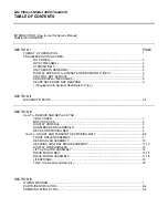
TABLE OF CONTENTS

SECTION I

PAGE

THEORY OF OPERATION

1

TROUBLESHOOTING GUIDES 

NO POWER..................................................................................................................... 2
NOISY TREADMILL......................................................................................................... 3
STRIDING BELT .............................................................................................................. 4
UNIT RESETS RANDOMLY ............................................................................................ 5
DISPLAY DOES NOT ILLUMINATE OR RESPOND TO INPUT....................................... 6
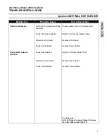
UNIT WILL NOT ELEVATE.............................................................................................. 7
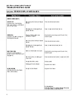
ERROR DISPLAY MESSAGES ....................................................................................... 8
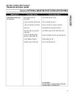
HEART RATE DOES NOT RESPOND ............................................................................ 9
( If Equipped with Optional Heart Rate Kit Tray )

SECTION II

DIAGNOSTIC TESTS................................................................................................................... 1-4

SECTION III

How To...REMOVE AND REPLACE THE

VENT COVER.................................................................................................................. 1
MOTOR COVER.............................................................................................................. 2
DISPLAY CONSOLE ....................................................................................................... 3
HANDLEBAR AND HANDRAILS...................................................................................... 4
DECK AND STRIDING BELT ........................................................................................... 5

How To...ADJUST AND TENSION THE STRIDING BELT .......................................................... 6-8

FRONT ROLLER ASSEMBLY ......................................................................................... 9
REAR ROLLER ASSEMBLY............................................................................................ 10
HEATSINK CONTROL BOARD ASSEMBLY ................................................................... 11,12
DISPLAY WIRE HARNESS ............................................................................................. 13
LIFT ACTUATOR ASSEMBLY ......................................................................................... 14
DRIVE MOTOR BELT ...................................................................................................... 15,16
DRIVE MOTOR ASSEMBLY............................................................................................ 17,18
LIFESPRINGS ................................................................................................................. 19
TRAY ( Optional Heart Rate Kit )...................................................................................... 20

SECTION IV

WIRING DIAGRAM ...................................................................................................................... 1
PARTS IDENTIFICATION ............................................................................................................ 2-4
COMMUNICATING BY FAX ......................................................................................................... 5,6

Содержание 4000

Страница 1: ...Model 4000 Treadmill Customer Support Services SERVICE MANUAL ...

Страница 2: ...ulse and Flexdeck are registered trademarks and Heart Rate Zone Training Lifespring and RELY ON IT are trademarks of Brunswick Corporation Polar is a registered trademark of Polar Any use of these trademarks without the express written consent of Life Fitness or the corresponding companies is forbidden M051 00K40 A030 10 98 ...

Страница 3: ...ceable part or assembly name and each page lists the Tools Required to complete that specific function Refer to Section IV to identify the proper name and number of the part you will now need to order to repair your machine A form to order by FAX has also been included in Section IV for your convenience To order a part call Life Fitness Customer Support Services any Monday through Friday from 8 00...

Страница 4: ...e harmful interference to radio communications However there is no guarantee that the interference will not occur in a particular installation If this equipment does cause harmful interference to radio or television reception which can be determined by turning the equipment off and on you are encouraged to try to correct the interference by one or more of the following measures Reorient or relocat...

Страница 5: ...f Equipped with Optional Heart Rate Kit Tray SECTION II DIAGNOSTIC TESTS 1 4 SECTION III How To REMOVE AND REPLACE THE VENT COVER 1 MOTOR COVER 2 DISPLAY CONSOLE 3 HANDLEBAR AND HANDRAILS 4 DECK AND STRIDING BELT 5 How To ADJUST AND TENSION THE STRIDING BELT 6 8 FRONT ROLLER ASSEMBLY 9 REAR ROLLER ASSEMBLY 10 HEATSINK CONTROL BOARD ASSEMBLY 11 12 DISPLAY WIRE HARNESS 13 LIFT ACTUATOR ASSEMBLY 14 D...

Страница 6: ...sed through the control board to the display console Display Console The display console is the user interface that allows selection from the various programs and options offered by the Treadmill The display console provides all of the Intelligence within the Treadmill controls the information displays and monitors the keypad and safety switches It determines the drive motor and lift actuator acti...

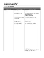
Страница 7: ...nt power source Plug treadmill into power source with proper electrical requirements See Operation Manual Line cord improperly seated in electrical outlet Inspect power connection at outlet Damaged line cord Replace line cord Faulty Display Console See Display Console symptom For Assistance Call Life Fitness Customer Support Services 1 847 451 0036 or 1 800 351 3737 ...

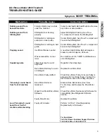
Страница 8: ...equire a break in period of approx 20 hours Run machine at 4 to 5 MPH to distribute wax onto Striding Belt Squeaking noise Lifesprings may be out of alignment Reposition the Lifesprings Drive Motor Belt may be worn or damaged Replace Drive Motor Belt Drive Motor Pulley shifted Check Drive Motor Pulley to insure Pulley is aligned with Front Roller Pulley Tighten the Set Screws to secure the Pulley ...

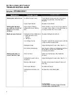
Страница 9: ...function Deck laminate is worn through Belt worn Replace Striding Belt and Deck Line Voltage too low Plug the Treadmill into a power source with the proper electrical requirements Striding Belt slips Adjust Striding Belt Tension See How To Drive Motor Belt slipping See How To Remove and Replace the Drive Motor Belt for proper Drive Motor Belt tensioning instructions Striding belt comes in contact ...

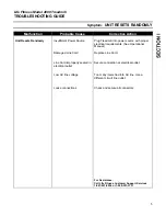
Страница 10: ...with proper electrical requirements See Operational Manual Damaged Line Cord Replace Line Cord Line Cord improperly seated in electrical outlet Secure connection at electrical outlet Low AC line voltage Too many items tied into AC line Use a different circuit line outlet Loose connections Check and secure all connectors For Assistance Call Life Fitness Customer Support Services 1 847 451 0036 or 1...

Страница 11: ...admill into power source with proper electrical requirements See Operation Manual Loose connection at Display Console or Control Board Secure connections at Display Console and Control Board Faulty Control Board With a volt meter check cable voltage at P1 Console cable for 8v DC pin 2 positive pin 8 negative Faulty Display Console Replace Display Console For Assistance Call Life Fitness Customer S...

Страница 12: ...Cord placement Faulty Lift Actuator limits Perform Lift Test See Diagnostics Defective Lift Actuator Replace Lift Actuator Faulty Control Board Replace Control Board Unit jammed at top of elevation Faulty Home Switch Perform Lift Home Switch Test Defective Home Switch Replace Home Switch Faulty Control Board Replace Control Board For Assistance Call Life Fitness Customer Support Services 1 847 451...

Страница 13: ...er OFF and ON at ON OFF switch Bad connection to Opto Speed Sensor Check all electrical connections Misaligned or damaged Opto Speed Sensor Adjust or replace Opto Speed Sensor BELT MOVING Occurs at interruption in power or when machine is just plugged in Spike or interruption in power Reset machine by turning power OFF and ON at ON OFF switch Bad connection or damaged Line Cord Check all electrica...

Страница 14: ...r Loose connection at Console Secure connection at Console and Handlebar User error Check Heart Rate kit operating instructions User may have an unusual heart beat Have different people try Transmitter chest strap Faulty Transmitter and or Receiver Heart Rate kit Replace Transmitter and or Receiver Heart Rate kit Faulty Display Console Replace Display Console Outside noise Cross talk Move unit to ...

Страница 15: ...10 Life Fitness Model 4000 Treadmill NOTES ...

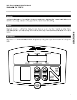
Страница 16: ...d with the optional Heart Rate Kit Tray Diagnostic procedures will test the Display Console Board as used in the final Treadmill assembly These procedures will insure proper functioning of the Console LED s Keys and Displays as well as identify the Console version Begin with the Treadmill turned OFF Hold the designated key during power up to enter into the chosen Diagnostic Menu Continued PURPOSE ...

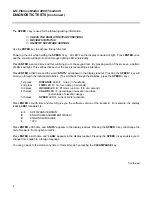
Страница 17: ...statistics To scroll back through the statistics press the SPEED σ key 1st press DISTANCE LED lit miles in hundreds 2nd press TIME LED lit motor on time in seconds 3rd press INCLINE LED lit lift motor run time 1 8 of a second 4th press CAL HR LED lit percentage of elevation and time percentage of elevation usage 5th press SPEED LED lit current limiter activation Press ENTER a fourth time and this ...

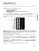
Страница 18: ...hopper wheel that is mounted on the motor When the LED is off the OPTO SPEED SENSOR is being blocked by a slot on the chopper wheel Normal function of the LED is that it flashes on and off as the drive motor turns during operation The fifth LED from the top will inform you if the unit is a 120v or a 220v unit When the LED is off the unit is 110v When the LED is on the unit is 220v The sixth LED fr...

Страница 19: ...their proper positions for the heart rate to display By pressing ENTER the users heart rate will appear on the display s readout INCLINE σ KEY Power up the unit while holding down the INCLINE σ key The striding belt will begin to move at 5 mph Grasp the handlebar and begin walking on the striding belt Walk forward taking the smallest steps possible This test will indicate the power draw on the tre...

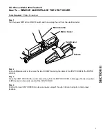
Страница 20: ... phillips screwdriver to remove the two SCREWS securing the sides of the VENT COVER to the MOTOR COVER Step 3 Grasp the VENT COVER in the center and pull away from the MOTOR COVER to disengage the two snap down CLIPS located on the inside center of the VENT COVER Step 4 Position the new VENT COVER into place and reverse steps 1 through 3 to return all parts to their proper locations Monocolumn Mot...

Страница 21: ...let Step 2 Remove the VENT COVER See How To Step 3 Use a phillips screwdriver to remove the SCREW securing the RETAINING PLATE and FIBERBOARD WEDGE in place on the MONOCOLUMN Step 4 Remove the four SCREWS securing the MOTOR COVER in place against the Treadmill FRAME Lift the MOTOR COVER from the machine Step 5 Place the new MOTOR COVER in position and reverse Steps 1 through 4 to return all parts ...

Страница 22: ...PLAY CONSOLE up from the MONOCOLUMN and unplug the 12 PIN CONNECTOR of the WIRE HARNESS from the back of the DISPLAY CONSOLE Step 5 Plug the 12 PIN CONNECTOR of the WIRE HARNESS protruding from the top of the MONOCOLUMN into the corresponding PC BOARD CONNECTOR located on the back of the new DISPLAY CONSOLE Once connected feed the excess CABLE of the WIRE HARNESS back into the top of the MONOCOLUM...

Страница 23: ...BAR to the top of the MONOCOLUMN Step 4 Loosen and remove the 2 top and the 2 1 2 bottom SCREWS securing the base of each of the two VERTICAL POSTS to the FOOT BRACKETS located on either side of the treadmill Step 5 Lift the entire HANDLEBAR HANDRAIL ASSEMBLY away from the machine and set it down on the floor Remove the SCREW securing each of the two VERTICAL POSTS to the foam padded HANDLEBARS an...

Страница 24: ...ne See How To Step 5 Remove the FRONT ROLLER ASSEMBLY See How To Step 6 Use a hex key wrench to loosen and remove the four SCREWS securing the top of the DECK to the FRAME ASSEMBLY Step 7 Remove the worn DECK and STRIDING BELT from the FRAME ASSEMBLY Step 8 Position a new DECK and STRIDING BELT in place and reverse Steps 1 through 6 to return all parts to their proper locations Refer to How to ADJ...

Страница 25: ...ioning place two pieces of tape exactly 38 5 inches 97 79 cm apart on both the right and left edges of the STRIDING BELT Step 2 Alternately tighten the two TENSIONING BOLTS 1 4 turn clockwise each until the distance between the tapes is 38 75 inches 98 425 cm which is the equivalent of 65 stretch Step 3 Adjust TRACKING CAUTION WHENEVER REMOVING OR REINSTALLING AN EXISTING STRIDING BELT DO NOT REMO...

Страница 26: ...MAY OVER STRETCH AND DAMAGE THE STRIDING BELT AS WELL AS PLACE AN UNNECESSARY LOAD ON THE REAR ROLLER BEARINGS Continued Life Fitness Model 4000 Treadmill CAUTION DO NOT MOVE OR PLACE YOUR HANDS UNDER THE UNIT WHILE THE MACHINE IS PLUGGED INTO AN ELECTRICAL OUTLET NOTE EACH ADJUSTMENT MADE TO ONE SIDE OF THE REAR ROLLER MUST BE MET WITH AN EQUAL AND OPPOSITE ADJUSTMENT TO THE OTHER SIDE OF THE REA...

Страница 27: ...IONING BOLTS are accessible from the holes provided in the ENDCAPS Step 2 Enter the Manual program and run unit for five minutes at 5 0 mph DO NOT run on the BELT Step 3 Using the speed decrease button bring the STRIDING BELT speed down to 2 mph With the STRIDING BELT speed at 2 mph tightly grasp the HANDRAILS and attempt to stall the STRIDING BELT If the STRIDING BELT slips continue to Step 4 if ...

Страница 28: ...rench to alternately turn the STRIDING BELT TENSIONING BOLTS 1 4 turn each counter clockwise until the STRIDING BELT is slackened enough to allow for removal of the FRONT ROLLER in the next Step Step 4 Slide the DRIVE MOTOR PULLEY BELT from the FRONT ROLLER ASSEMBLY PULLEY Lift the worn FRONT ROLLER ASSEMBLY from the EXTRUSION BRACKETS and from within the STRIDING BELT to remove it from the unit S...

Страница 29: ... OF THE MOUNTING BRACKET TO LOCATE ITS ORIGINAL PLACEMENT THIS WILL HELP WHEN RE TENSIONING THE STRIDING BELT Step 5 Remove the worn REAR ROLLER from the machine Step 6 Position the new REAR ROLLER against the MOUNTING BRACKETS and use a hex key wrench to install the TENSIONING SCREWS and WASHERS by alternately turning the SCREWS clockwise an equal number of turns until the STRIDING BELT is snug b...

Страница 30: ...it from the electrical outlet Step 2 Remove the VENT COVER See How To Step 3 Remove the MOTOR COVER See How To Step 4 Ground yourself to the machine by positioning an ANTI STATIC GROUNDING STRAP around your wrist and attaching the other end alligator clip to a MOUNTING SCREW or a connecting GROUND WIRE SCREW Step 5 Unplug the six CONNECTORS shown in the illustration from the HEATSINK CONTROL BOARD...

Страница 31: ...e POSITIVE and NEGATIVE WIRE CONNECTORS leading from the DRIVE MOTOR ASSEMBLY to the CAPACITOR Step 8 Remove the two MOUNTING SCREWS securing the HEATSINK CONTROL BOARD ASSEMBLY to the MOTOR PAN Step 9 Carefully lift the malfunctioning HEATSINK CONTROL BOARD ASSEMBLY from the machine and set aside Step 10 Place the new HEATSINK CONTROL BOARD ASSEMBLY into position and reverse Steps 1 through 8 to ...

Страница 32: ...REW Step 7 Tuck the 12 PIN CONNECTOR which was disconnected from the DISPLAY CONSOLE into the top of the MONOCOLUMN Withdraw the DISPLAY WIRE HARNESS from the MONOCOLUMN through the large hole at the base of the MONOCOLUMN Step 8 Unplug the 12 PIN CONNECTOR from the HEATSINK CONTROLLER BOARD ASSEMBLY Step 9 Feed the new DISPLAY WIRE HARNESS through the MONOCOLUMN from the large hole at the base of...

Страница 33: ...ect the large LIFT MOTOR NUT from the pins holding it to the LIFT FRAME ASSEMBLY by removing the two HAIR PIN CLIPS and PUSH BOLTS Step 7 Remove the HAIR PIN CLIP and CLEVIS PIN securing the unthreaded end of the LIFT ACTUATOR to the FRAME Step 8 Carefully lift the malfunctioning LIFT ACTUATOR and remove it from the machine Step 9 Check the new LIFT ACTUATOR distance from the top of the threaded p...

Страница 34: ...OSITION OF THE REAR ROLLER ON THE INSIDE OF THE MOUNTING BRACKET TO LOCATE ITS ORIGINAL PLACEMENT THIS WILL HELP WHEN RE TENSIONING THE STRIDING BELT Using a hex key wrench ALTERNATELY loosen the two TENSIONING SCREWS and WASHERS securing each side of the REAR ROLLER to the REAR ROLLER MOUNTING BRACKETS an EQUAL number of times counter clockwise until the STRIDING BELT is slackened enough to allow...

Страница 35: ...ENSIONING GUAGE Belt tension 100 lb 5 lb The DRIVE BELT tension can be adjusted by loosening or tightening the LOCK NUT of the TENSIONING BOLT located next to the LIFT ACTUATOR Step 9 Reverse Steps 1 through 4 to return all parts to their proper positions and refer to How To ADJUST AND TENSION THE STRIDING BELT for proper BELT tensioning instructions CHECKING THE DRIVE BELT PULLEY ALIGNMENT It is ...

Страница 36: ...ABLE from the black retaining clip attached to the metal heat sink on the CONTROL BOARD ASSEMBLY Disconnect the SENSOR CABLE CONNECTOR from the CONTROL BOARD Note the orientation of the SENSOR CABLE CONNECTOR on the CONTROL BOARD for reference during installation Step 6 It will now be necessary to relieve the DRIVE MOTOR BELT tension by removing the LOCK NUT on the TENSIONING BOLT located next to ...

Страница 37: ...OR PULLEY and the FRONT ROLLER PULLEY The faces of the two PULLEYS should be in line coplanar If the PULLEYS are not aligned loosen the two SET SCREWS on the DRIVE MOTOR PULLEY and adjust as necessary Once aligned recheck the SHAFT KEY and PLASTIC FAN positions per Step 9 above and tighten the two DRIVE MOTOR PULLEY SET SCREWS Step 11 Install the 1 4 20 nylon insert LOCK NUT onto the TENSIONING BO...

Страница 38: ...LIFESPRING Loosen and remove the SCREW through the access hole Step 5 Lift the entire LIFESPRING ANTI ROTATION CLIP ASSEMBLY from the machine Slide the worn LIFESPRING out of the ANTI ROTATION CLIP and replace with a new LIFESPRING Step 6 Reposition the LIFESPRING ANTI ROTATION CLIP ASSEMBLY in place taking note that the lower lip of the ANTI ROTATION CLIP rests against the FRAME of the Treadmill ...

Страница 39: ...RAY slowly away from the back of the DISPLAY CONSOLE while the extended arms of the TRAY continue to rest on the HANDLEBARS of the treadmill Step 4 Unplug the 3 PIN CONNECTOR of the Heart Rate Monitor Receiver HARNESS located within the TRAY from the matching 3 PIN CONNECTOR on the back of the DISPLAY CONSOLE Step 5 Swing the TRAY down while lifting the extended arms of the TRAY from the HANDLEBAR...

Страница 40: ...21 Life Fitness Model 4000 Treadmill NOTES ...

Страница 41: ...1 Life Fitness Model 4000 Treadmill WIRING DIAGRAM Life Fitness Model 4000 Treadmill ...

Страница 42: ...00 Motor Shroud AK40 00037 0002 Console Assembly AK40 00057 0001 R Eng Met AK40 00057 0004 R Frn Met Overlay Bezel AK40 00058 0001 Eng Eng AK40 00058 0004 Frn Met Handlebar w Grips OK40 01092 0001 Handrail Tube OK40 01006 0001 Mono Column OK40 01093 0001 Stop Key Clip AK40 00035 0000 ...

Страница 43: ...OK40 01165 0001 Extrusion LT OK40 01165 0002 Handrail Mount OK40 01034 0001 Push Cap Kit GK45 00002 0008 Vent Cover AK40 00039 0001 Tray w Heart Rate optional GK40 00002 0006 Tray optional OK40 01095 0001 Telemetry Receiver SK40 00045 0001 Display Cable AK36 00017 0000 ON OFF Switch AK40 00052 0000 Removable Safety Switch 0017 00032 0191 ...

Страница 44: ...Assembly AK40 00027 0000 Deck Assembly AK40 00025 0001 Rear Roller OK40 01013 0000 Stride Belt OK40 01177 0000 TECKS PAK OK40 01026 0001 Optical Sensor AK40 00031 0000 Drive Motor Assembly SK40 00051 0001 120v 60Hz AK40 00051 0002 220v 50Hz 240v Lift Actuator OK40 01132 0000 120v 60Hz OK40 01132 0001 220v 50Hz 240v Heatsink Assembly SK40 00033 0001 R 120v 60Hz AK40 00033 0002 R 220v 60Hz 240v ...

Страница 45: ...lem we have included for your convenience a FAX form on the following page Simply make a copy or copies of the FAX sheet and fill in the necessary information You may FAX us at any time 24 hours a day to either of the numbers shown A Life Fitness service representative will process your order or respond to your problem as quickly as possible ...

Страница 46: ...ER FORM ITEM NO PART NUMBER DESCRIPTION QUANTITY 1 2 3 4 5 6 PRODUCT TROUBLESHOOTING PRODUCT NAME SERIAL NO DETAILED DESCRIPTION OF PROBLEM PRODUCT NAME SERIAL NO DETAILED DESCRIPTION OF PROBLEM TIME RECEIVED TIME COMPLETED TECHNICIAN NAME CUSTOMER SUPPORT SERVICES 10601 W Belmont Ave Franklin Park IL 60131 PHONE 800 351 3737 Toll Free or 847 451 0036 FAX 800 216 8893 Toll Free or 847 288 3702 ...

Страница 47: ...7 Life Fitness Model 4000 Treadmill NOTES ...

Отзывы: