background image

Service

Operation & Maintenance Manual  43

Cycle Components

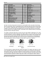
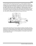
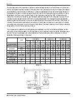
The structure of the air-cooled cooling cycle is shown in the below. 

The unit is equipped with semi-hermetic screw compressor developed especially for applications in air-condi-
tioning. The construction of the compressor is shown in the below.

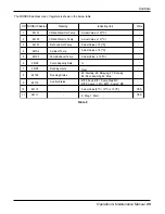
SERVICE

No.

PART

No.

PART

No.

PART

No.

PART

(1)

Compressor

(7)

Flow Control Device

(13)

Oil Level Switch

(19)

Relief Valve

(2)

Condenser

(8)

Flow Control Device

(14)

Oil Solenoid Valve

(20)

Temperature Sensor

(3)

Reciever

(9)

Dryer

(15)

Oil Flow Switch

(21)

Low Pressure Switch

(4)

Oil Filter

(10)

Evapolator

(16)

Discharge Temp. Sensor

(22)

Water Flow Switch

(5)

Oil Seperator / Economizer

(11)

Oil Heater

(17)

Oil High Pressure Switch

(23)

Ref. Solenoid Valve

(6)

Flow Control Device

(12)

Oil Level Sight Glass

(18)

Anti-freezing Switch

(24)

Check Valve

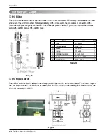
Compressor

Table 13

Fig. 21

Fig. 20

Содержание RCAW

Страница 1: ...peration Maintenance Manual completely before Operating Maintenance the product Operating Maintenance must be performed in accordance with the national wiring standards by authorized personnel only Please retain this Operating Maintenance for future reference after reading it thoroughly R134a Chiller Air cooled Screw ...

Страница 2: ...hine on off control 30 START UP Pre Start up 31 Start up Procedure 32 Operation Limits 34 OPERATION Sequence of Operation 37 Sensors 42 SERVICE Cycle Components 43 Control System 56 Maintenance 67 TROUBLE SHOOTING 68 APPENDIX Wiring Diagram 76 Cycle Diagram 77 Check List 78 Air cooled Screw Operation Maintenance Manual TABLE OF CONTENTS ...

Страница 3: ...e The seriousness is classified by the following indications We do not have any responsibility for any failure caused by careless management and natural disaster and power cord failure regardless of warranty period The content in the manual could be changed for the improvement of product without notice Meanings of symbols used in this manual are as shown below This symbol indicates the possibility...

Страница 4: ... be damaged Do not reconstruct to change the settings of the protection devices If the pressure switch thermal switch or other protection device is shorted and operated forcibly or parts other than those specified by LGE are used fire or explosion may result Ventilate before operating chiller when gas leaked out It may cause explosion fire and burn Securely install the cover of control box and the...

Страница 5: ...ignated refrigerant and oil is pro hibited Do not use undesignated refrigerant freezer oil and brine It can have a critical effect on the compressor and component defects If you would like to use a substitute for the refrig erant please contact the manufacturer Redesigning the control box is prohibited Lock the control box with possible locking device and if you need to open the control box inevit...

Страница 6: ...age to heat exchanger tubes Use appropriate brine solutions in cooler fluid loops to prevent the freezing of heat exchangers when the equipment is exposed to temperatures below 32 F 0 C Do not attempt to unbraze factory joints when servicing this equipment Cut lines with a tub ing cutter as required when performing ser vice Compressor oil is flammable and there is no way to detect how much oil may...

Страница 7: ...bles that are too small may leak generate heat and cause a fire Do not use the product for special purposes such as preserving foods works of art etc It is a consumer chiller not a precision refriger ation system There is risk of damage or loss of property Keep the unit away from children It can cause the injury such as cutting the finger Also the damaged fin may result in degradation of capacity ...

Страница 8: ...ose of the packing materials Packing materials such as nails and other metal or wooden parts may cause stabs or other injuries Tear apart and throw away plastic packaging bags so that children may not play with them If children play with a plastic bag which was not torn apart they face the risk of suffocation Turn on the power at least 12 hours before starting operation Starting operation immediat...

Страница 9: ... is found stop operating the unit and contact the service center Insufficient check can cause fire explosion and defect Use appropriate tools Use appropriate tools used for the repair and make sure to calibrate the measuring devices precisely before use If you use inappropriate tools etc it can cause an accident Be careful of air cooling type heat exchanger Because the condenser of the air cooling...

Страница 10: ... remove these devices may cause component damage Harsh chemical household bleach or acid cleaners should not be used to clean outdoor or indoors coils of any kind These cleaners can be very difficult to rinse out of the coil and can accelerate corrosion at the fin tube interface where dissimilar materials are in contact If there is dirt below the surface of the coil use the Environmentally Sound C...

Страница 11: ...g among menu items are accomplished by the manipulation of the arrow keys To see the detail information of the each menu item press the arrow key To start up the chiller start button must be pressed for more than 3 sec onds Similarly to shut down the chiller stop button must be pressed for more than 3 seconds Main Menu System Setting User Setting Content System Setting Main Display Par Setting Con...

Страница 12: ...main menu The temperature readings include chilled water entering tem perature CHW In Temp outdoor air temperature Ambient Temp compressor exhaust temperature Exhaust Temp chilled water leaving temperature CHW Out Temp and condenser refrigerant leaving temperature Condensate Temp Compressor running hours Comp Running Hrs means accumulated running hours of the compressor This value can be initializ...

Страница 13: ...meters Temp Setting include chilled water leaving temperature reference setpoint Target Temp compressor shutdown temperature Outage Temp compressor restart temperature Restart Temp The chilled water leaving temperature reference setpoint is desirable temperature configured by the operator The allowable range of the temperature is 5 C 12 C 41 F 53 6 F The default value of it is 7 C 44 6 F Setting V...

Страница 14: ...auto the chiller runs according to programmed schedule Contrary when the start mode is hand the chiller runs according to key manipulation by operator or remote signal The control mode can be either local or remote When the mode is local the chiller runs according to key manipulation by operator Contrary when the mode is changed to remote a remote contact is substitute the key operation and con se...

Страница 15: ...be different Consequently the PLC evaluates the normality of the contactors by checking inputs after making outputs to the contactors be on The antifreeze S W indicated the contact status from the anti freezing switch The switch is normally closed and opens when temperature is under setting value The PLC considers the openness of the switch to be anti freezing switch alarm The pressure means the s...

Страница 16: ...rgency switch is in normal position When the switch is pushed by operator the emergency stop switch opens and all output from the PLC are disconnected The PLC consid ers the openness of the switch to be emergency alarm The discrete outputs generated from the PLC are also displayed on the screen cut Alarm means the alarm notification to external devices by the PLC If any system alarm is detected by...

Страница 17: ...ue at affirm entry is changed to clear by pressing the arrow keys Pressing ENT key after the value is changed into clear makes the clearance of the alarm history be effective Fig 5 Alarm Display Delay Setting User Setting Content Alarm History 1 10 5E Alarm 2009 03 03 Date 12 53 50Time Clear Alarm History 2 10 5E Alarm 2009 03 03 Date 12 53 50Time Clear Alarm History 10 10 5E Alarm 2009 03 03 Date...

Страница 18: ...n be cleared in this screen After pressing SET key the value at running hrs clear entry is changed to clear by pressing the arrow keys Pressing ENT key after the value is changed into clear makes the clearance of the alarm history be effective Fig 6 System Setting Main Display Par Setting Content Temp and Hours Correction Chilled In Chilled Out Condensate Temp Ambient Temp Exhaust Temp Limit Comp ...

Страница 19: ...n off2 can be configured From the transition points fan full opening means the condenser refrigerant leaving temperature setpoint for running all condenser fans When actual temperature is over the setpoint all condenser fans must run Similarly the fan off1 means the condenser refrigerant leaving temperature setpoint for running 8 condenser fans And the fan off2 means the condenser refrigerant leav...

Страница 20: ...defined delay the PLC starts the compressor sequentially The outage delay is delay between minimization of the compressor capacity and compressor stop When the PLC receive stop signal from operator the PLC reset the capacity valves into minimum capacity position And after the defined delay the PLC stop the compressor sequentially Oil preheat is startup delay of the chiller after receiving start si...

Страница 21: ...ich user interface Through the LCD interface the operator can monitor the status of chiller operation and control in detail And the control configurations also can be performed through the LCD interface For the monitoring and the configuration 7 menu items are prepared in the LCD display from main menu to parameter setting as shown in the below picture In the below pic ture amendable menu contents...

Страница 22: ...reheating Delay Schedule Program Amendable Item Remote Control Input Oil Check System Input Comp Contactor Contact Inputs Low Temp Switch Input Pressure Switch Input Phase Protect Input Chilled Water Flow Input Differential Pressure Input Compressor Overload Input Fan Contactor Contact Inputs Emergency Switch Input Alarm Output Comp Contactor Outputs Solenoid Valve Output Fan Contactor Outputs Pum...

Страница 23: ...r RTDI CN6 LED OUTPUT1 Auto Manual Control Automatic Control ON Manual Control OFF OUTPUT2 Local Remote Control Remote Control ON Local Control OFF OUTPUT3 Remote Start Input Run ON Stop OFF OUTPUT4 Start Interval Lapse Delaying ON Complete OFF OUTPUT5 Compressor Recycle Recycle Stop ON Running OFF OUTPUT6 Condenser Coil Warning ON Contamination Normal OFF OUTPUT7 MODBUS Application Applying ON No...

Страница 24: ...osition DIP switch have to indicate MODBUS slave device address The 8 position DIP switch represents 8 bit hexa number with two digits in inverted value For example the factory setting position shown in the below picture switch2 8 ON and switch 1 OFF represent 0x7E and its inverted value is 0x01 The factory setting means MODBUS slave address of the chiller is 0x01 D2 D3 D4 D5 D6 D7 D8 D9 1 2 3 4 1...

Страница 25: ...ons of the connectors are shown in the above pictures and detail descriptions of the connectors are shown in the below table The power of discrete outputs is 220VAC and the power of the discrete inputs is 24VDC CN5 CN3 CN1 CN2 CN4 Fig 13 CN6 MODBUS Fig 14 ...

Страница 26: ...ame Ground System Alarm M1 Contactor Main Contactor M2 Contactor Contactor M3 Contactor Wye Contactor 25 Magnet Comp Loading Valve 50 Magnet Comp Loading Valve 75 Magnet Comp Loading Valve Water Pump Common 220VAC Live Connector Pin Description Wire No CN3 DO 2 O09 O10 O11 79 80 Fan1A1B O12 O13 O14 O15 O16 COM 81 82 83 85 88 87 7 Fan2A3A Fan2B3B SV2 Magnet Valve Common 220VAC Live Table 3 Table 4 ...

Страница 27: ...witch I08 38 Phase Protector I09 39 Chilled Water Flow Switch I10 40 Differential Pressure Switch I11 41 Comp Overload Internal Protector I12 42 Fan1A1B I13 43 Fan2A3A I14 44 Fan2B3B I15 45 I16 46 24V 26 24VDC Positive 24G 27 24VDC Ground M1 Contactor Main Contactor M2 Contactor Contactor Emergency Switch Connector Pin Description Wire No CN5 DI 2 I01 I16 26 24VDC Positive 24G 27 24VDC Ground 24V ...

Страница 28: ...t Temperature Ambient Temperature Refrigerant Cond Out Temperature Table 7 The MODBUS communication capability is provided by standard Using the MODBUS communication the chiller can be integrated in conventional BMS network The MODBUS also can be translated to LonWorks or BACnet using 3rd party translator for flexible connectivity to BMS network The communication configuration of the MODBUS commun...

Страница 29: ...mp Exhaust Temp Comp Capacity Rate Running Hours Running Status Control Status 2 46102 3 46103 4 46104 5 46105 6 46106 7 46108 8 46109 9 46110 10 46115 11 06111 Actual Value x 10 C Actual Value x 10 C Actual Value x 10 C Actual Value x 10 C Actual Value x 10 C Hour 65 Starting 66 Delaying 67 Running 68 Shut downing 69 Stop BIT0 Fault BIT1 Comp Main MC BIT2 Comp MC BIT3 Comp Y MC Actual Value 5 C 1...

Страница 30: ...ay you want press the SET key and then ENTER to move to the row you want to change Then use the to change the value and press the to change the set value After changing the value press the ENTER button After changing the set value switch from the Hand Control mode to the Auto Control mode to schedule the unit to operate at the set time The operating key to change the setting is as follows Set Chan...

Страница 31: ...n evaporator and condenser Open all water flow valves to the evaporator Turn on the chilled water pump manually measure the water pressure drop across the evaporator and check that water flow is correct per the design flow rates Check all electrical connections in control panel to be sure they are tight and provide good electrical contact Connections are tightened at the factory but can loosen eno...

Страница 32: ...n the start switch installed on the door of control panel Check and inspect the status of the LEDs of the PLC Programmable Logic Controller and the HMI Haman Machine Interface unit The HMI unit should display welcome screen after switching on Check and inspect the voltage monitoring relay inside of the power panel The relay should not indicate any fault code Using the HMI unit configure chilled wa...

Страница 33: ... Ω Resistance Ω Temperature F RTD Temperature Vs Resistance Table Temperature F 328 310 292 274 256 238 220 202 184 166 148 130 112 94 76 58 40 22 4 14 32 18 49 50 68 86 104 122 140 158 176 194 212 230 248 266 284 302 320 338 356 374 382 410 103 90 428 446 464 482 500 518 536 554 572 590 608 626 644 662 680 698 716 734 752 183 17 22 80 107 79 186 32 27 08 111 67 190 45 31 32 115 54 194 07 35 53 11...

Страница 34: ...operate the motor of the compressor when the imbalance among the phases exceed 5 The formula to calculate the voltage imbalance is as follows Voltage Imbalance 100 x Max Voltage from average voltage Average Voltage Max Voltage from average voltage is the absolute value of the maximum gap from the average voltage of the 2 phases Example Voltage source 400 3phase 1 2 3 50Hz 12 405V 23 394V 31 410V A...

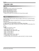
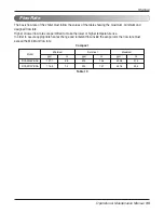
Страница 35: ...Higher or lower flow rates are permitted to make the lower or higher temperature rise In order to assure appropriate heat exchange and turbulent flow inside the evaporator the flow rate must exceed the Minimum flow rate gpm l s gpm l s gpm l s RCAW100 BAA RCAW090 BAA 116 9 7 4 234 14 7 467 6 29 5 107 7 6 8 215 13 6 430 8 27 2 Maximum Model Minimum Norminal Table 10 Compact ...

Страница 36: ...RT Compact model 40 100 RT Pressure drop kPa Water flow rate l s 0 5 10 15 20 25 30 35 40 45 50 55 60 0 50 100 150 200 250 300 350 400 450 500 40 RT 40 RT 80 RT 80 RT 60 RT 60 RT 50 RT 50 RT 70 RT 70 RT 90 RT 90 RT 100 RT 100 RT 40 RT 60 RT 50 RT 70 RT 80 RT 90 RT 100 RT 40 RT 80 RT 60 RT 50 RT 70 RT 90 RT 100 RT Compact model 40 100 RT Pressure drop ft wg Water flow rate gpm Chilled water pressur...

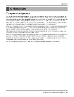
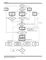
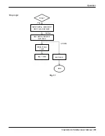
Страница 37: ...and transits to delta start after 4 seconds During starting the compressor the compressor contactors are also checked whether there is any problem with the feedback from the contactors and SV1 oil solenoid valve is opened for proper oil circulation After the start normal controls are initiated The normal controls include capacity control mid pressure refrigerant con trol for motor cooling condense...

Страница 38: ...ng Setpoint MV1 ON 25 Alarm M3 OFF DELTA Start Stop logic No No Yes Yes 0 5 Sec 4 Sec 9 Sec Yes 3 Sec Yes No No Flow S W 30 60 sec No Yes Yes M1 ON M2 ON Capacity Control Mid pressure Refrigerant Valve Control Alarm Control Condenser Fan Control SV2 Y DELTA START STOP Start Contactor Check Flow Check Water Temp Check Comp Contactor Check Stop Fig 16 ...

Страница 39: ...Operation Operation Maintenance Manual 39 Fig 17 MV2 OFF MV3 OFF MV1 ON SV2 OFF M2 OFF M1 OFF SV1 OFF Water Pump OFF Fan OFF 4 10Min Yes Stop logic 60 Sec stop MV1 OFF Stop ...

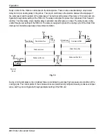
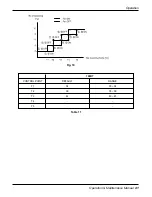
Страница 40: ...t The delay is also config urable through user setting of the HMI unit The delay is designed to protect the cooling cycle of the chiller from improper oil circulation especially at low ambient condition During running compressor the condenser fans are controlled to get proper high pressure side condition of the cooling cycle The control points of the condenser fans are determined by refrigerant le...

Страница 41: ...Operation Operation Maintenance Manual 41 Fig 19 Table 11 CONTROL POINT DEFAULT RANGE T1 34 30 34 T2 39 35 39 T3 44 40 45 T4 T5 100RT ...

Страница 42: ... Detect Temperature F Resistance Ω Resistance Ω Resistance Ω Temperature F RTD Temperature Vs Resistance Table Temperature F 18 49 103 90 183 17 22 80 107 79 186 32 27 08 111 67 190 45 31 32 115 54 194 07 35 53 119 40 197 69 39 71 123 24 201 29 43 87 127 07 204 88 48 00 130 89 208 45 52 11 134 70 212 02 56 19 138 50 215 57 60 25 142 29 219 12 64 30 146 06 222 65 68 33 149 82 226 17 72 33 153 58 22...

Страница 43: ...o PART No PART No PART 1 Compressor 7 Flow Control Device 13 Oil Level Switch 19 Relief Valve 2 Condenser 8 Flow Control Device 14 Oil Solenoid Valve 20 Temperature Sensor 3 Reciever 9 Dryer 15 Oil Flow Switch 21 Low Pressure Switch 4 Oil Filter 10 Evapolator 16 Discharge Temp Sensor 22 Water Flow Switch 5 Oil Seperator Economizer 11 Oil Heater 17 Oil High Pressure Switch 23 Ref Solenoid Valve 6 F...

Страница 44: ...e ratio to avoid losses in efficiency due to under or over compression The screw compressor is equipped with 4 step capacity control system The capacity control system is consist ing of a modulation slide valve piston rod cylinder piston and piston rings The slide valve and the piston are connected by a piston rod The principle of operation is using the oil pressure to drive the piston in the cyli...

Страница 45: ... started at full load capacity it may result in over current start The capillary is used to maintain and restrain a suitable amount of oil flow into the cylinder If the oil filter cartridge capillary or modulation solenoid valves are not working well in the capacity control sys tem this may result in the abnormality and ineffectiveness of the capacity control system The main functions of the lubri...

Страница 46: ...ature circumstance it could cause compressor in heavy duty to be started up resulting less oil pressure in oil line to load the compressor The better solution is to have higher condensing temperature in a short time by warming up the oil The compressor is equipped two oil sight glasses as a standard one is the oil high level sight glass and the other is the oil low level sight glass The normal oil...

Страница 47: ... leak and recharge Replace transducer Add refrigerant Repair replace as needed Remove and clean strainer Replace switch Open valve or replace if defective Check wiring Repair or replace motor s if defective Clean coil Check wiring Repair or replace valve if defective Clean condenser Add refrigerant Replace control Clean or replace Replace or repair Evaluate load requirements Check loader solenoid ...

Страница 48: ...lying the cleaning utensil across the pin Periodical water cleaning Periodically cleaning the pin with water helps the maintenance of the coil installed on the coast or industrial site But due to the fragility of the installed coil you must rinse the coil with water at low speed in order to prevent any damage to the coil It is recommended to clean once every one to two months Condenser If you use ...

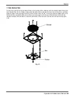
Страница 49: ... the condenser fan is as shown in the picture as follows Apply the grease on the exposed part of the motor to protect it from the rain You have to apply the grease again on the fan axis and then reinstall the Shroud Also there is an axis support on the fan axis of the fan motor which must be inserted accurately at this location for maximum performance of the fan motor And then the bolt must be fir...

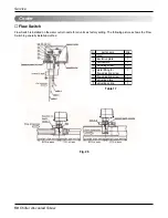
Страница 50: ...zzle for all units as factory setting The following pictures shows the Flow Switch in generally installed method Fig 26 Table 17 parts name Qty cover insulation plate microswitch adjusting screw metal fitting for flow adjusting screw flow adjusting screw actuating plate adjusting spring 1 1 1 1 1 1 1 1 ...

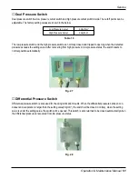
Страница 51: ... be closed automatically when the differential pressure is recovered from low pressure status Dual pressure switch has low pressure cutout switch and high pressure cutout switch inside The cutoff points can be adjustable The factory setting values are shown in the below The low pressure switch and the high pressure switch are normally closed and tripped to opening when the detected pressure exceed...

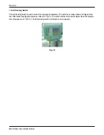
Страница 52: ... to detect too low water temperature The switch is normally closed and tripped when the chilled water leaving temperature is under 35 6 F 2 C The switch returns to the normal status when the tempera ture increases over 41 F 5 C The Anti freezing switch is installed on the evaporator Fig 29 ...

Страница 53: ...he chiller must be removed and vacuumed Charging the refrigerant Insert the coupling to the refrigerant charging port In order to avoid the damage to the tube from residual water freezing within the evaporator circulate the water in the evaporator EVA while charging the refrigerant to the designated amount For the amount of refrigerant to charge refer to the installation manual or PDB Charging the...

Страница 54: ...is recommended to disas semble the oil filter and wash the oil filter mesh Oil Flow Switch The oil flow switch is also installed on the oil separator in oil return line to the compressor The setpoint range of the flow switch covers 3 4 4 2 l min at increasing flow and 3 0 3 8 l min at decreasing flow Maximum flow rate of the oil flow switch is 67l min Item Name Note Qty Bolt M10 x 40L 8 Service fl...

Страница 55: ...rned on when the unit is operating to pass the oil to the compressor and off when the operation stops to prevent the oil from back flowing The oil heater prevents poor lubrication due to too low viscosity The oil heater is also installed on the oil sepa rator The 150W oil heater has 220VAC power input Fig 32 Fig 33 Include Cable wire Include DIN plug wire 3 3 68 95 85 75 54 45 25 281 72 138 38 35 ...

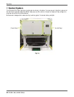
Страница 56: ...ow The power panel in the left is composed of the electrical components related to 400VAC main power and the control in the right is composed of low voltage com ponents such as the PLC and the HMI unit Both panels are designed to be water proof by dual door system The panels comply with IP55 Control Panel Power Panel Fig 34 ...

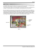
Страница 57: ...ng inrush current is reduced by 1 3 of direct starting method The line voltage VL of the both of wye and delta winding configuration is 400VAC but the phase voltages VP of the wye winding configuration is reduced by 1 3 of the delta winding configuration Additionally the line current IL is also reduced by 1 3 of the delta winding configuration Consequently the current of the wye winding configurat...

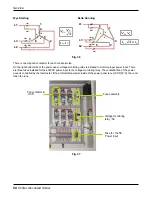
Страница 58: ...the 5E Power input Fig 36 Fig 37 There is one magnetic contactor for each condenser fan On the right bottom side of the power panel voltage monitoring relay is installed to monitor proper power input There are three fuses installed for the 400VAC power input to the voltage monitoring relay The ventilation fan of the power panel is controlled by the thermostat If the ambient temperature inside of t...

Страница 59: ... factory settings are shown in the below table n Condenser Fan OCR The condenser fan OCR is also thermal type and used to protect the condenser fan from overload condition The OCR contact used for the control system is normally closed and the OCR contact switch is to be opened if it detects exces sive current The OCR needs manual reset by switch on the OCR to be recovered to normal after tripping ...

Страница 60: ...tective The others are mandatory When any abnormal condition is encountered the type of abnormal condition and abnormal value detected are displayed instead of normal display Some examples of the abnormal conditions are shown in the below Along with the selectivity of protection reset method after any abnormal condition invocation can be configured through 4 position DIP switches The functions of ...

Страница 61: ...ing point and tripping delay are also configurable through another rotary switch on the voltage monitoring relay The factory setting of the rotary switches are shown in the below table Rate Voltage 380VAC 400VAC Over Voltage Value 416VAC 440VAC Over Voltage Delay 4S Under Voltage Value 342VAC 360VAC Under Voltage Delay 4S Table 23 Table 22 REV UNBAL AUTO 5S 1S ON OFF ON OFF ON OFF ON OFF Reverse p...

Страница 62: ...ay to check power supply of 220V to the controller Assist Relay is as follows Compressor Contactor Compressor Contactor controls the start stop and static range of the compressor motor when the product is operating Rated voltage of Compressor Contactor is 400V Fig 40 Fig 41 ...

Страница 63: ...Service Operation Maintenance Manual 63 Fan Contactor Fan Contactor controls the start stop and static range of the fan motor when the product is operating Rated voltage of Fan Contactor is 400V Fig 42 ...

Страница 64: ...rection the power to the output is recovered On the internal door of the control panel operator can access the HMI unit Along with the HMI unit power indication lamp and start stop switch are installed on the door The start stop switch is to switch on or off the control power to the control system and the power supply status is indicated through the power lamp Sight glass for the HMI unit PLC Emer...

Страница 65: ...ck case The PLC is supplied 24VDC power from the SMPS Switched Mode Power Supply on the right side The relay is to confirm proper 220VAC power supply and start stop switch which is installed on the door is positioned at start The ventilation fan of the control panel runs permanently after power on Control fuse Control Relay Switched Mode Power Supply Fig 44 ...

Страница 66: ...e product The shapes and character istics are as follows Ventilation Fan Ventilation Fan is attached on both sides of the Power Box and the Control Box This fan responds to the temperature increase within both boxes while the product is operating and sends the air outside to prevent any issues from tempera ture increase within each box Fig 45 Fig 46 ...

Страница 67: ...k 6 Cooling tower cleanness Check Clean Annual clean 7 Refrigerant system leakage Check Monthly check 8 Oil filter Check Replace Check every 6 months Clean if necessary 9 Dryer filter Check Replace Annual replacement 10 Oil Level Check Annual check 11 Oil color Check Replace 12 Compressor insulation Check Annual check 13 Temperature sensor Check Check every 6 months 14 Compressor bearing Check Che...

Страница 68: ...nvocation has to be checked You can find whether any alarm is invoked through the HMI unit Follow specific alarm trouble shooting procedure if any alarm is invoked Normally the compressor of the chiller will cycle according to the chilled water leaving temperature the compressor shutdown temperature and the compressor restart temperature But the case where the compressor runs too long without cycl...

Страница 69: ...start delay time Check chilled water temp out Check water flow Check for leak and add refrigerant Replace the contactors Purge water loop Remove refrigerant and recharge Check Alarm status See separate alarm trouble shooting procedure and follow trouble shooting instructions Check for temperature inputs See operation and control Check capacity control overrides Check the PLC input channels also to...

Страница 70: ...ressor The delay is adjustable through delay setting of the HMI unit Shortage of oil must be inspected firstly When the chiller runs under low ambient temperature without enough pre heating much amount of oil can be remained in evaporator instead of the oil separator In this case oil must be added up to the oil separator Low differential pressure between the evaporator and the condenser will not g...

Страница 71: ...ance Missing phase 5E Alarm Repair or replace CHW pump Remove air and supplement water CHW line side valve open Flow switch setting or device error CHW flow switch input switch off after the CHW pump run CHW pump malfunction Shortage of CHW volume CHW line side valve closed Flow switch setting or device error Waterflow Alarm Remove over charging refriger ant Repair or replace high pressure switch ...

Страница 72: ...un Oil dryer clogged Oil service valve error or closed Oil flow switch error Controller DI error Shortage of oil Replace oil level switch Repair or replace controller Supplement oil Oil level switch input switch off 120 sec ond after the compres sor run Oil level switch error Controller DI point error Shortage of oil System Oil Alarm Replace M1 contactor Check voltage check condenser fan motor cle...

Страница 73: ...ternal protec tive switch Check ambient temperature Trip of compressor internal protector switch off by high discharge temperature Refrigerant flow rate insufficient Controller AI point error Comp error Internal protective switch error Too high ambient temperature Increase CHW flow or replace pump Increase set value of chilled CHW temp out Lower anti freezing set value Replace anti freezing switch...

Страница 74: ...B motor check magnetic contactor or relay Check FAN1A1B lock FAN1A1B magnetic contactor contact input or overload relay con tact input switch off after the compressor run Malfunction of FAN1A1B Condenser FAN1A1B overload FAN1A1B Alarm Replace FAN2A3A motor check magnetic contactor or relay Check FAN2A3A lock FAN2A3A magnetic contactor contact input or overload relay con tact input switch off after...

Страница 75: ...pen Ambient temperature sensor close Ambient temperature sensor open Malfunction of FAN2B3B Condenser FAN2B3B overload Malfunction of FAN4B5B Condenser FAN4B5B overload Sensor line is short Malfunction of Sensor Sensor line is cut out or loose Malfunction of Sensor Sensor line is short Malfunction of Sensor Sensor line is cut out or loose Malfunction of Sensor Sensor line is short Malfunction of S...

Страница 76: ...EEZING LP HP CHILLED WATER FLOW HIGH LOW DIFFERENTIAL INT69 5E OLF1A OLF2A OLF2B FN1A FN2A FN2B 101 OLF1B OLF3B FN1B FN3A FN3B 104 110 102 105 111 103 106 112 EMERGENCY SWITCH RTD1 24V 24V RTD1 RTD2 RTD2 RTD3 RTD3 RTD4 RTD4 RTD5 RTD5 2 1 4 3 6 5 8 7 10 9 24V G IO1 IO2 IO3 IO4 IO5 IO6 IO7 IO8 IO9 I10 I11 I12 I13 I14 I15 I16 COM O01 O02 O03 O04 O05 O06 O07 O08 O09 O10 O11 O12 O13 O14 O15 O16 O17 O18...

Страница 77: ... Comp magnetic switch 1 F1 F3 CF1 CF2 R1 CCH1 THC SV1 SV2 M2 M1 M3 M1 M2 M3 Comp magnetic switch 2 Comp magnetic switch 3 Y Fan1A Fan4A over current relays Comp over current relay Fan1A Fan4A magnet contactors FN1A FN4A FN1B FN4B Fan1B Fan4B magnet contactors OLC1 OLF1A OLF4A OLF1B OLF4B Fan1B Fan4B over current relays L0 Power indicator lamp Emergency switch SW1 HP LP 5E Low pressure switch Rever...

Страница 78: ...itch LEGEND OH DESCRIPTION HPS LPS Low pressure switch Temperature sensor TS Oil level sensor OLS Oil flow switch OFS Water flow switch Relief valve WFS AFS Anti freezing switch OS S Insulation Oil sol valve Sight glass Refrigerant sol valve Economizer Flash gas tank 11 Check valve Service valve 3 2 6 4 5 7 1 9 10 8 Oil Pipe Line Low Pressure Line High Pressue Line TS OS S Liquid Injection Line HP...

Страница 79: ... for installation and operation Contents Description PJT name Address Installing contractor Sales office Start up performer Contents Description PJT name Address Installing contractor Sales office Start up performer Contents Description Unit Model Serial Compressor A Model Serial Compressor B Model Serial ...

Страница 80: ...ere is no leakage No No Yes All piping is connected properly Yes All chilled water valves are open Check Contents Is there any physical damage Yes No ơ If yes where Will this prevent start up Yes No All screws and bolts are tight Yes No Power supply agrees with the unit nameplate Yes No Electrical power wiring is installed properly Yes No Unit is properly grounded Yes No Electrical circuit protect...

Страница 81: ...water inlet temperature Brine concentration No Yes There is no abnormal noise or vibration lbs Additional oil charge Chilled water inlet temperature No Yes Alarm is not generated and the unit operates normally No Yes Voltage imbalance is within 2 No Yes Voltage at terminal block is within 10 No No Yes There is leakage of refrigerant Comp Condenser Economizer Cooler Yes All refrigerant line service...

Страница 82: ...P No MFL63291701 Printed in Korea After reading this manual keep it in a place easily accessible to the user for future reference ...

Отзывы: