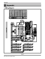
Appendix
78
Chiller Air-cooled Screw
n
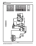
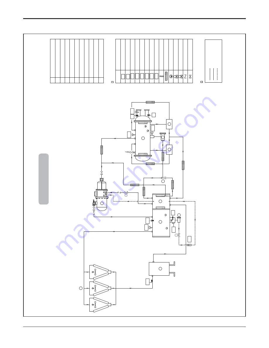
Cycle Diagram
Fig. 49
DESCRIPTION
No
Compressor
1
Condensing coil
2
Receiv
e
r
3
Oil Filter
4
Oil separ
ater
5
Ejector f
o
r Oil Retur
n
6
Expansion De
vices
7,8
Filter Dr
ier
9
Ev
apor
ator
10
SYMBOL
Oil heater
High pressure s
w
itch
LEGEND
OH
DESCRIPTION
HPS
LPS
Lo
w pressure s
w
itch
T
emper
ature sensor
TS
Oil le
v
el sensor
OLS
Oil flo
w
s
w
itch
OFS
W
ater flo
w
s
witch
Relief v
a
lv
e
WFS
AFS
Anti-freezing s
w
itch
OS
S
Insulation
Oil sol.
v
a
lv
e
Sight glass
Refr
iger
ant sol.
v
a
lv
e
Economiz
er (Flash gas tank)
11
Chec
k v
a
lv
e
Ser
vice v
a
lv
e
3
2
6
4
5
7
1
9
10
8
Oil Pipe Line
Lo
w Pressure Line
High Pressue Line
TS
OS
S
Liquid Injection Line
HPS
TS
AFS
LPS
TS
TS
WFS
OFS
OH
OLS
Pipe
line
11
RCA
W090,100

