1
10-5
CHECKING FLOW CHART BY FAILURE
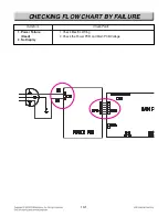
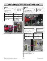
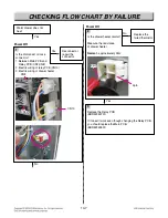
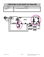
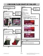
Oven does not heat, F-11
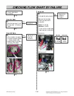
Power Off
Is the disconnect or loose
connector?
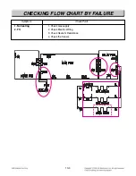
1. Between Main PCB and
Relay PCB (CN7, CN8)
2. Electric wiring of relay PCB (CN10)
3. Electric wiring of electric element
Gas Valve &
Drawer Heater
Gas Valve &
Drawer Heater
Bake glowbar
igniter
No
Yes
Yes
Yes
CN10
CN10
CN10
CN10
CN10
CN10
CN10
CN10
CN10
CN10
CN10
CN10
CN10
CN10
CN10
CN10
CN10
CN10
CN10
CN10
CN10
CN10
CN8
CN8
CN8
CN8
CN8
CN8
CN8
CN8
CN8
CN8
CN8
CN8
CN8
CN8
CN8
CN8
CN8
CN8
CN8
CN8
CN8
CN8
CN7
CN7
CN7
CN7
CN7
CN7
CN7
CN7
CN7
CN7
CN7
CN7
CN7
CN7
CN7
CN7
CN7
CN7
CN7
CN7
CN7
CN7
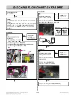
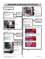
Power Off
2
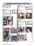
Is the glowbar ignitor
normal?
Measure the resistance
of each glowbar
(The resistance is shown on next page)
No
Reconnect or
repair the
connector
Replace the
failed glowbar
Broil glowbar igniter
Bake glowbar igniter
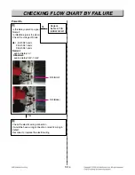
Power Off
3
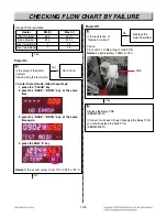
Is the Gas valve normal?
Measure the resistance
of Gas valve
(The resistance is shown on next page)
No
Replace the
Failed Valve
Broil Gas Valve
Pin No.
Bake Gas Valve
1pin
1pin
1pin
1pin
1pin
1pin
1pin
1pin
1pin
1pin
1pin
1pin
1pin
1pin
1pin
1pin
1pin
1pin
1
4
2
3
3pin
3pin
3pin
3pin
3pin
3pin
3pin
3pin
3pin
3pin
3pin
3pin
3pin
3pin
3pin
3pin
3pin
3pin
N
N
N
N
N
N
N
N
N
N
N
N
N
N
N
N
N
N
WH
WH
WH
WH
WH
WH
WH
WH
WH
WH
WH
WH
WH
WH
WH
WH
WH
WH

