- 41 -
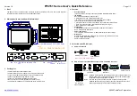
After reset the unit, take steps to PCB as follows
for temperature compensation.
1. In the case of 6871JB1431 ( by July 2007)
: Compensate with replacing RCR1
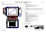
2. In the case of EBR34917102
(from Aug 2007)
: Compensate with Jump wire cutting
* Change RCR1
* Cutting of jumper wire
Temp. Compension
RCR1
Temp. Compensation
Cutting both jumpers affords a 2…
temperature compensation
+ 1.0 deg
+ 1.0 deg
JUMP WIRE
Ressult
+ 2.5 deg
180 k‰
+ 2 deg
56 k‰
+ 1.5 deg
33 k‰
+ 1 deg
18 k‰
+ 0.5 deg
12 k‰
Current
Colder
JCR1
JCR2
Replace
Damper
Enter the TEST 3 MODE
Is the voltage between
Pins 4 and pin 12 of
CON3 like as below?
Voltage of Compressor
115 V
pin4 to pin12
Ressult
Test Point
Yes
Yes
Pin12
BK
Pin4
BL
CON3
Содержание LFX25960SB
Страница 12: ... 12 4 WIRING DIAGRAM ...
Страница 65: ...9 1 Main PCB Assembly 6871JB1431 by July 2007 CON1 CON2 CON3 CON4 CON5 CON6 CON7 9 PCB ASSEMBLY 65 ...
Страница 66: ...EBR34917102 from Aug 2007 66 CON4 CON5 CON6 CON7 CON1 CON2 CON3 ...
Страница 75: ...P No 3828JL8795A APR 2006 Printed in Korea ...


