3-16
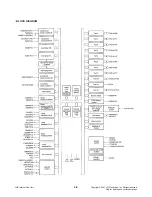
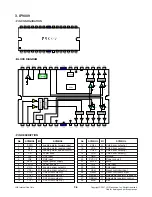
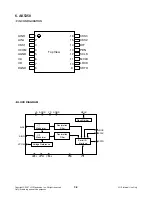
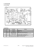
• BLOCK DIAGRAM
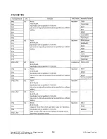
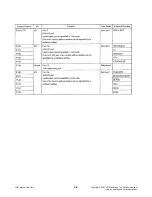
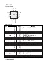
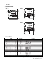
• PIN FUNCTION
Terminal
No.
SYMBOL
Description
Functions
1
D
Drain terminal
MOSFET drain
2
S
Source
MOSFET Source
3
GND
Ground terminal
Ground
4
Vcc
Power supply terminal
Input of power supply for control circuit
5
SS/OLPDelay at Overload/
Overload P
rotection and Soft Start peration Time set up
Soft Start set up Terminal
6
FB
Feedback terminal
Constant Voltage Control Signal Input,
Burst(intermittent) mode Oscillation Control
7
OCP/BD
Overcurrent Protection Input/
Overcurrent Detection Signal Input
Bottom Detection Terminal
Bottom Detection Signal Input
10. STR-X6757N
Copyright © 2007 LG Electronics. Inc. All right reserved.
Only for training and service purposes
LGE Internal Use Only

