- 41 -
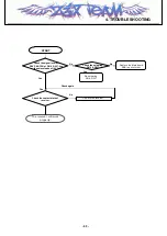
START
No
Power is supplied to
the board?
Yes
Refer to
Power On Trouble
Connection between
FPCB and boards is OK?
No
Reconnect FPCB
Yes
CN401 or CN3 is soldered well?
No
Re-solder the CN401
or CN3
Yes
Paths of LCD control
signals are OK?
No
Re-solder
the EMI filter
Yes
FPCB is OK?
No
Replace the FPCB
Yes
Connection between
FPCB LCD Module is OK?
No
Resolder
The CN3
Yes
After changing the board,
LCD Display is OK?
No
The board is broken.
Change the board.
Yes
LCD Module is out of order.
Change the LCD Module.
Z3X-BOX.COM
Содержание CE500
Страница 1: ...Service Manual Model CE500 Service Manual CE500 Date September 2005 Issue 1 0 Z 3 X B O X C O M ...
Страница 3: ... 4 Z 3 X B O X C O M ...
Страница 14: ...3 Technical Brief 15 3 1 4 Digital Baseband DBB Processor Block diagram of the AD6532 Z 3 X B O X C O M ...
Страница 36: ...4 TROUBLE SHOOTING 37 Test Point VEXT VRTC VMEM VINT VSIM VPLL VUSB VABB VTCXO VCORE VMIC Z 3 X B O X C O M ...
Страница 77: ...4 TROUBLE SHOOTING 78 5 Check Tx I Q TXQP TXQN TXIN TXIP U704 Test Point Z 3 X B O X C O M ...
Страница 85: ...Note 86 Z 3 X B O X C O M ...
Страница 93: ... 94 8 PCB LAYOUT Z 3 X B O X C O M ...
Страница 94: ... 95 8 PCB LAYOUT Z 3 X B O X C O M ...
Страница 95: ... 96 Z 3 X B O X C O M ...
Страница 103: ...9 CALIBRATION 104 L Standalone Test Equipment Setup Oscilloscope Z 3 X B O X C O M ...
Страница 105: ... 106 Z 3 X B O X C O M ...
Страница 127: ...Note 128 Z 3 X B O X C O M ...


