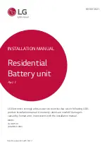
manualshive.com logo in svg
background image

ENGLISH

4

1.3  Warning Label

Product/warning label and Battery Control Unit’s traceability label are behind the front cover. 
The front cover opens by turning the front cover handle counterclockwise. Battery Modules’ 
traceability labels are attached to the side of the Battery Modules.

1.  Product/Warning Label

2.  Traceability label

2-1. Battery Control Unit

2-2. Battery Module

EH153064P8S7DMA

○○○○○○○○○○

SH077064P8S7BMA

○○○○○○○○○○

A

SH077064P8S7BMA

○○○○○○○○○○

B

1.4  Qualifi ed Personnel

This guide for the tasks and procedures described herein is intended for use by skilled staff  

only. A skilled staff  is defi ned as a trained and qualifi ed electrician or installer who has all of 

the following skills and experience:

•  Knowledge of the functional principles and operation of on-grid and off -grid 

(backup) systems

• 

Knowledge of the dangers and risks associated with installing and using electrical 
devices and acceptable mitigation methods

• 

Knowledge of the installation of electrical devices

• 

Knowledge of and adherence to this guide and all safety precautions and best 
practices

•  Qualifi cation specifi ed in battery warranty fi le

: BLG RESU-certifi cation in the battery website

: Knowledge of local installation standards 

: Electrical license for battery installation required by the country or state 

• 

Repair the battery by disassembly is possible only at the LG Service Center or by 

a person who is specially authorized separately from the installation qualifi cation

2  Product Introduction

2.1  Technical Data

2.1.1 

Dimensions and Weight

BLG RESU10HP

Part Number

TLB00983101

Width

504 mm (19.8”)

Height

817 mm (32.2”)

Depth

295 mm (11.6”)

Weight 

1)

111 kg (244 lbs)

1) Battery pack weights may vary slightly.

2.1.2 Performance 

Electrical Characteristics

Usable Energy 

1)

9.6 kWh

Battery Capacity

64.1 Ah

Voltage Range

350 to 450 VDC

Absolute Max. Voltage

595 VDC

Max. Current (charging/discharging)

14.3A @ 350V

Max. Power (charging/discharging)

5 kW

Peak Power 

2)

 (only discharging) 

7 kW for 10 sec.

Peak Current (only discharging) 

20.9 A for 10 sec. 

Communication Interface

RS485/ CAN

DC Disconnect 

Circuit Breaker

Connection Method 

Spring Type Connector

User Interface 

LEDs for Normal and Fault Operation

Operating Conditions

Installation Location 

Indoor/Outdoor

Operating Temperature 

charge

14°F to 122°F (-10°C to 50°C)

discharge

-4°F to 122°F (-20°C to 50°C)

Operating Temperature 
(Recommended)

59°F to 86°F (15°C to 30°C)

Storage Temperature 

-22°F to 140°F (-30°C to 60°C), acceptable for 7 
days in total
-4°F to 113°F (-20°C to 45°C), acceptable for the 

fi rst 6 months

-4°F to 86°F (-20°C to 30°C), acceptable for months 
7~12

Humidity

5% to 95%

Altitude

Max. 6,562 ft (2,000 m)

Cooling Strategy 

Natural Convection

Certifi cation

Safety

Cell
Battery
Pack

UL1642
CE / RCM / IEC 62619 / UL1973 / 
IEC62477-1

Emissions

FCC

Hazardous Materials Classifi cation

Class 9

Transportation

UN38.3

Ingress Rating

IP55

※ Test Conditions: Temperature 25°C/77°F, at the beginning of life.
※ Energy is measured under specifi c conditions from LG Electronics (0.3CPCV/0.3CP).

1)  Value for battery pack only. Maximal usable energy at the AC output may vary by condition, 

such as inverter effi  ciency, confi guration and temperature.

2) Peak current excludes repeated short duration (less than 10 sec. of current pattern).

Содержание BLGRESU10HP

Страница 1: ...lectronics strongly advises users to exercise due care in following LGE s product installation manual A warranty claims are invalid if damage is caused by human error inconsistent with the installation manual MODEL LG HBP10H BLGRESU10HP Read in conjunction with Part 2 ...

Страница 2: ... 4 Installation Location 3 1 5 Clearance 3 1 6 Tools Safety Gear Required 3 1 7 Appearance and Dimensions 3 1 8 System Clearance 3 1 9 Installing the Battery Pack 3 2 Installation process for Remote Monitoring Device RMD 3 2 1 Prepare for installation using RMD 3 2 2 Installation via RMD 3 3 Cable Connections 3 3 1 Cable Configuration 3 3 2 Guide for cable connection and setting the DIP switch 3 3...

Страница 3: ...uct or the product s packaging since the product may be damaged Do not place any foreign objects on top of the Battery Pack and on the cooling fin Do not put the battery pack upside down on the ground Do not connect the power cables at terminal the block in the opposite direction Do not charge or discharge a damaged battery If the Product is installed in a garage or carport ensure there is adequat...

Страница 4: ...ght BLG RESU10HP Part Number TLB00983101 Width 504 mm 19 8 Height 817 mm 32 2 Depth 295 mm 11 6 Weight 1 111 kg 244 lbs 1 Battery pack weights may vary slightly 2 1 2 Performance Electrical Characteristics Usable Energy 1 9 6 kWh Battery Capacity 64 1 Ah Voltage Range 350 to 450 VDC Absolute Max Voltage 595 VDC Max Current charging discharging 14 3A 350V Max Power charging discharging 5 kW Peak Po...

Страница 5: ...ring the protective qualities shall not be used Protective items that become contaminated with grease oil flammable liquids or combustible materials shall not be used The garment manufacturer s instructions for care and maintenance of arc rated apparel shall be followed Arc rated apparel shall be stored in a manner that prevents physical damage damage from moisture dust or other deteriorating agen...

Страница 6: ...inconsisten t with the installation manual 4 Pull out the bundled items including the Module Connecting Plate 5 Pull out Battery Module B 6 Pull out Battery Module A 7 Optional Pull out the parts for wall mounting CAUTION According to regional regulations several people may be required for moving equipment 3 1 4 Installation Location Requirements There must be no highly flammable or explosive mate...

Страница 7: ...he inverter NOTE An external DC isolator may be installed within the clearance zone Minimum clearances may be greater according to local regulations Inverter Ceiling Floor 500mm 20 300mm 12 300mm 12 500mm 20 300mm 12 300mm 12 Inverter Ceiling Floor Inverter Ceiling 500mm 20 300mm 12 300mm 12 500mm 20 300mm 12 300mm 12 300mm 12 Inverter Ceiling Floor Standing type Wall Mounting type 3 1 9 Installin...

Страница 8: ...n e HE RE Pla ce th e sp ac er In th e lin e HE RE Pla ce th e sp ac er In th e lin e HE RE Pla ce th e sp ac er In th e lin e HE RE Pla ce th e sp ac er In th e lin e HE RE Pla ce th e sp ac er In th e lin e HE RE Place the spacer In the line HERE Place the spacer In the line HERE Place the spacer In the line HERE Spacer used for assmbly ang disassembly TOP Pla ce th e sp ac er In th e lin e HE R...

Страница 9: ... in e HE RE Pl ac e th e sp ac er In th e lin e HE RE Pl ac e th e sp ac er In th e lin e HE RE Pl ac e th e sp ac er In th e lin e HE RE Pl ac e th e sp ac er In th e lin e HE RE Pl ac e th e sp ac er In th e lin e HE RE Pl ac e th e sp ac er In th e lin e HE RE C Remove a spacer A Grab here E Remove another one in the same way D Settle slowly B Lift just few mm 13 Remove one spacer by lifting on...

Страница 10: ...not to drop the bolts into the pack at this stage Connector for Ethernet cable Hole 2 Hole 1 22 Assemble the adapter or cap according to regional regulations Insert the RMD ethernet cable through Hole 2 and connect the cable Then proceed to Section 3 2 Installation for Remote Monitoring Device RMD Internal cable Hole 2 Communication cable Hole 1 Power cable 23 Assemble the adapter or cap according...

Страница 11: ...nge Bolts x12 with a torque of 5N m Pl ac e th e sp ac er In th e lin e HE RE Pl ac e th e sp ac er In th e lin e HE RE Pl ac e th e sp ac er In th e lin e HE RE Pl ac e th e sp ac er In th e lin e HE RE Pl ac e th e sp ac er In th e lin e HE RE Pl ac e th e sp ac er In th e lin e H ER E Pl ac e th e sp ac er In th e lin e H ER E Pl ac e th e sp ac er In th e lin e H ER E Pl ac e th e sp ac er In ...

Страница 12: ... th e sp ac er In th e lin e HE RE Pl ac e th e sp ac er In th e lin e HE RE Pl ac e th e sp ac er In th e lin e HE RE 12 Double check the alignment of the Battery Control Unit Pl ac e th e sp ac er In th e lin e HE RE Pl ac e th e sp ac er In th e lin e HE RE Pl ac e th e sp ac er In th e lin e HE RE Pl ac e th e sp ac er In th e lin e HE RE Pl ac e th e sp ac er In th e lin e HE RE Pl ac e th e ...

Страница 13: ...e sp ac er In th e lin e HE RE Pl ac e th e sp ac er In th e lin e HE RE Pl ac e th e sp ac er In th e lin e HE RE Pl ac e th e sp ac er In th e lin e HE RE Handle Front Cover 19 Open the front cover Hold the handle and turn it counterclockwise M5 PH Bolt 6ea Front Protection Cover 20 Loosen 6 bolts and remove the Front Protection Cover Be careful not to drop the bolts into the pack at this stage ...

Страница 14: ...n button If you don t have your account please visit LG ESS Battery website and make an account https www lgessbattery com us in case of North America https www lgessbattery com au in case of Australia https www lgessbattery com eu in case of all EU countries in general https www lgessbattery com de in case of Germany https www lgessbattery com it in case of Italy https www lgessbattery com es in ...

Страница 15: ... key at the e mail address you provided 7 Enter your authentication key within 3 minutes to verify your account 8 Click the Confirm button L J K 9 Select the Owner option 10 Enter your ID and Password 11 Click the Sign In button 3 2 2 Installation via RMD Click the link on the RESU Monitor website to download the APK file of the RESU Installer App NOTE Depending on the device RESU Installer App ma...

Страница 16: ... is complete click the Next button 3 2 2 5 QR Code Scan The QR code scanning method is as follows Select Prime Fixed at 2 FLEX Select from 2 to 4 S N of consecutive QR codes are automatically displayed Maximun 5 When the QR code registration is complete click the Next button If the scanned serial number matches the actual serial number it will proceed to the next section There are three 3 QR codes...

Страница 17: ...n and Battery Status Check IoT Hub Connection String Enter the unique string provided to you in order to access the Azure IoT Hub cloud server The string format is as follows HostName emashub azure devices net DeviceId XXXX SharedAccessKey OOOO For more information on how to obtain strings refer to Section 3 2 1 2 Obtaining IoT Hub String Server Connection Check Check the server connection Battery...

Страница 18: ...tch Communication Termination resistor all downwards for single pack When you install two packs refer to the appendix about setting for communication termination resistor 3 Section C DIP switch for setting primary secondary packs Raise all DIP switch upward when you want to use as a primary pack And also when you want to use as a secondary pack lower the switch on the right side only when viewed f...

Страница 19: ......

Отзывы: