


ENGLISH
8
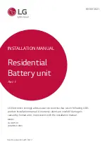
Standing bracket_1
RESU1
0H
Prime
Drill
Template
Standing bracket 1
3.
Remove the Drill template and fi x the
Standing bracket 1 on the wall.
Battery Module B
Label
Wall
Rear
Front
Front
Rear
Battery Module Direction
4. Place Battery Module B on the rear
side of Module Connect plate.
* The side without bolts is the front
of the Battery Module.
*
Check the label to confi rm the
battery pack is of B. Label is
attached on the left side of Battery
Module.
Fron
t
Fron
t
Battery Module A
Label
Front
Front
Battery Module B
Battery Module A
TOP VIEW
Rear
Front
Wall
5. Place Battery Module A on the front
side of Module Connect plate. The
Rear side of each Battery Module
should face each other. After that,
remove the Spacer between the wall
and Battery Module.
*
Check the label to confi rm the
Battery pack is of A. Label is
attached on the left side of Battery
Module.
Fron
t
Fron
t
Module Support BRKT
Fron
t
Fron
t
6. Assemble Module Support BRKTs
using 6 bolts each.
* Tighten the M6 Flange Bolts (x12)
with a torque of 5N·m.
Pla
ce t
he
spa
cer
In the line HERE
Plac
e th
e sp
acer
In the line HERE
Plac
eth
e sp
acer
In the line HERE
Pla
ce t
he
spa
cer
In the line HERE
Pla
ce t
he
spa
cer
In the line HERE
Pla
ce t
he
spa
cer
In the line HERE
Plac
e th
e sp
acer
In the line HERE
Plac
e th
e sp
acer
In the line HERE
Plac
e th
e sp
acer
In the line HERE
Plac
e th
e sp
acer
In the line HERE
Pla
ce t
he
spa
cer
In the line
HERE
Pla
ce t
he
spa
cer
In the line
HERE
Pla
ce t
he
spa
cer
In the line HERE
Pla
ce t
he
spa
cer
In the line HERE
Battery Control Unit
Battery Modules
7. Remove bubble wrap from
connectors of Battery Control Unit
and the warning label of Battery
Modules.
Pla
ce t
he
spa
cer
In the line HERE
Pla
ce t
he
spa
cer
In the line HERE
Plac
e th
e sp
acer
In the line HERE
Plac
e th
e sp
acer
In the line HERE
Plac
e th
e sp
acer
In the line HERE
Plac
e th
e sp
acer
In the
line HERE
Pla
ce t
he
spa
cer
In the line HERE
Pla
ce t
he
spa
cer
In the line HERE
Plac
e the spac
er
In the line HERE
Plac
e the spac
er
In the line HERE
Plac
e the spac
er
In the line HERE
Plac
e the spac
er
In the line HERE
Spacer
(used for assmbly ang disassembly)
TOP
Pla
ce t
he
spa
cer
In the line HERE
Plac
e th
e sp
acer
In the line HERE
Plac
e th
e sp
acer
In the line HERE
Pla
ce t
he
spa
cer
In the line HERE
Plac
e the spac
er
In the line HERE
Plac
e the spac
er
In the line HERE
Pla
ce the spa
cer
In the line HERE
Plac
e the spac
er
In the line HERE
Plac
e the spac
er
In the line HERE
Spacer
(used for assmbly ang disassembly)
TOP
Spacer
Spacer
TOP VIEW
8. Place the spacers on the position
marked with label on Battery
Modules.
Plac
ethe spac
er
In the
line HERE
Plac
ethe sp
acer
In th
eline HERE
Plac
e the spac
er
In the line HERE
Plac
e the
spa
cer
In t
he line HERE
Plac
e the spac
er
In t
he line HERE
Pla
ce the spa
cer
In t
he line
HERE
Plac
e the spac
er
In the line HERE
Pla
ce the spa
cer
In the line HERE
Plac
e the spac
er
In the line HERE
Plac
e the spac
er
In the line HERE
Plac
e the spac
er
In the line HERE
Plac
e the spac
er
In the line HERE
Battery Control Unit
Battery Control Unit
Plac
ethe spac
er
In the
line HERE
Plac
e the spac
er
In
the line HERE
Plac
e the spac
er
In t
he
line HERE
Plac
e the spac
er
In the line
HERE
Plac
e the spac
er
In the line HERE
Plac
e the spa
cer
In the line HERE
Plac
e the spac
er
In the line HERE
Plac
e the spa
cer
In the line HERE
Plac
e the spac
er
In the line HERE
Pla
ce the spa
cer
In the line HERE
Plac
e the spac
er
In the line HERE
Pla
ce the spa
cer
In the line HERE
Battery Control Unit
9. Place the Battery Control Unit on
top of the spacers, and align with the
Battery Module.
* Be careful not to break the
connector between the spacers and
the Battery Control Unit.
Содержание BLGRESU10HP
Страница 19: ......


