


46
MUL
TI V Split Rooftop Unit Installation Manual
Due to our policy of continuous product innovation, some specifications may change without notification.
©LG Electronics U.S.A., Inc., Englewood Cliffs, NJ. All rights reserved. “LG” is a registered trademark of LG Corp.
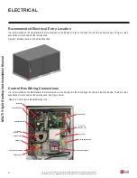
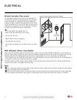
Recommended Electrical Entry Location
It is recommended by the manufacturer that electrical service be brought into the unit through the end wall, as shown below. There are three
penetrations into the cabinet that are required.
Figure 32: Electrical Entry in the Split Rooftop Units.
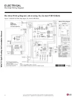
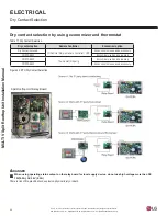
ELECTRICAL
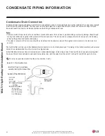
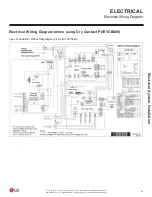
Control Box Wiring Connections
It is recommended by the Manufacturer that electrical service be brought into the unit through the end wall, as shown below. There are three
penetrations into the cabinet that are required. See Figure below.
Figure 33: Control box in the Split Rooftop Unit.
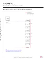
Main PCB
SUB PCB(HR UNIT)
SUB PCB(Main PCB)
Transformer
208-230V
→
24V
T/B-Economizer
T/B-Motor
T/B-Communication/ Remote
T/B-Main Power
Economizer(Honey Well)
T/B-DO (Digital Output)
Relay PCB
Dry Contact
208-230V
→
24V
HR UNIT PCB