


45
Electrical System Installation
Due to our policy of continuous product innovation, some specifications may change without notification.
©LG Electronics U.S.A., Inc., Englewood Cliffs, NJ. All rights reserved. “LG” is a registered trademark of LG Corp.
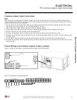
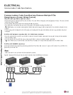
Communication Cable Connection
Note:
When connecting the communications bus between the outdoor unit, RTU(s), and heat recovery unit(s), it does not matter what physical path or
route the wire takes. The installer may use discretion when choosing the order the components are connected to the communications bus, but must
maintain the daisy chain and polarity configuration.
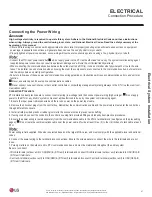
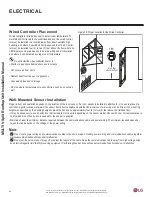
1. Access hole for the communications cable and the power cable are located at the bottom of the RTU. Remember that the communications
cable and the power cable must enter the control box through different knockouts.
2.
Field-install a plastic or rubber grommet in the knockout hole to prevent wire chaffing.
3. If using conduit, connect the conduit to the control box using field-provided fittings and industry best-practice procedures.
4. Provide at least three (3) to four (4) inches of slack cable at each RTU.
5. Secure the communications cable to the inside surface of the control box using a field provided nylon wire clamp.
6. Strip approximately quarter of an inch of insulation from each communications cable conductor. At each RTU, insert the conductors under
the terminal screw.
7. Securely tighten the terminal screws to prevent the communications conductors from coming loose from the terminal block.
8. Secure the communications cable in appropriate locations outside the Split Rooftop Unit to prevent damage to the cable or injury to main-
tenance personnel.
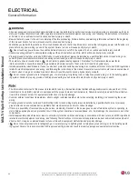
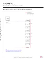
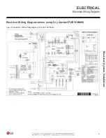
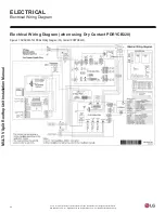
Figure 30: Location of Power Wiring / Communications Cable Terminals in the Split Rooftop Units.
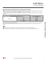
Power Wiring and Communications Cable Location
RTU Terminal Block
L(L1) N(L2)
A
-
-
-
-
-
-
A
B
B
GND 12V
DRY2
DRY1
INTERNET
IDU
SODU
Outdoor Unit Terminal Block
Power Input
208-230V /
60 Hz / 1 Phase
Ground
YL RD
A B
BK
Wired Controller
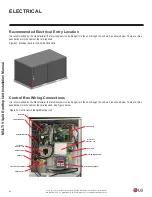
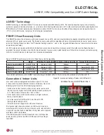
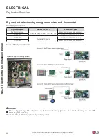
Figure 31: Terminal Block in the Split Rooftop Units.
ELECTRICAL
RTU Communications Cable Connections
T/B - DO (Digital Output)
Power Supply High Voltage (208/230V)
Economizer (Optional) High Voltage (208/230V)
Fan Motor High Voltage (208/230V)
Wired Remote Controller
Transmission
Connections