117
July 2010 50PJ350 Plasma
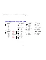
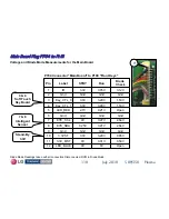
Voltage and Diode Test for the Main Board
Diode Mode Check with the Board Disconnected.
Main Board Plug P703
Main Board Plug P703
“
“
LVDS
LVDS
”
”
Voltages
Voltages
P703 “Main Board” Connector to P121 "Control Board”
Note:
There are no voltages in
Stand-By mode.
Blue Pins indicate 10 bit
differential video signal
0.49V
2.87V
DISP_EN
25
1.03V
0.59V
PC_SER_CLK
23
0.76V
1.35V
RA2+
21
0.77V
1.27V
RB2+
19
0.77V
1.22V
RC2+
17
0.77V
1.23V
RCLK2+
15
0.77V
1.26V
RD2+
13
0.77V
1.25V
RE2+
11
2.6V
3.3V
Module_SCL1
9
Gnd
Gnd
Gnd
7
Gnd
Gnd
Gnd
5
2.6V
3.29V
ROM_RX
3
Open
n/c
n/c
1
Diode
Check
Run
Label
Pin
Gnd
Gnd
Gnd
26
1.49V
3.3V
PC_SER_DATA
24
0.77V
1.13V
RA2-
22
0.77V
1.21V
RB2-
20
0.77V
1.26V
RC2-
18
0.77V
1.23V
RCLK2-
16
1.09V
1.21V
RD2-
14
1.09V
1.23V
RE2-
12
2.6V
3.3V
Module_SDA1
10
Gnd
Gnd
Gnd
8
Gnd
Gnd
Gnd
6
2.6V
3.3V
ROM_TX
4
Open
n/c
n/c
2
Diode
Check
Run
Label
Pin
1
1
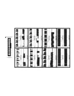
Pin 1 front row right side
Note: There are no wires
into pins 1 and 2.


