background image

LGE Internal Use Only

Copyright ©2009 LG Electronics. Inc. All right reserved. 
Only for training and service purposes

- 3 -

SAFETY PRECAUTIONS

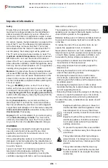
Many electrical and mechanical parts in this chassis have special safety-related characteristics. These parts are identified by      in the
Schematic Diagram and Exploded View.
It is essential that these special safety parts should be replaced with the same components as recommended in this manual to prevent
Shock, Fire, or other Hazards. 
Do not modify the original design without permission of manufacturer.

General Guidance

An 

isolation Transformer should always be used

during the

servicing of a receiver whose chassis is not isolated from the AC
power line. Use a transformer of adequate power rating as this
protects the technician from accidents resulting in personal injury
from electrical shocks.

It will also protect the receiver and it's components from being
damaged by accidental shorts of the circuitry that may be
inadvertently introduced during the service operation.

If any fuse (or Fusible Resistor) in this TV receiver is blown,
replace it with the specified.

When replacing a high wattage resistor (Oxide Metal Film Resistor,
over 1W), keep the resistor 10mm away from PCB.

Keep wires away from high voltage or high temperature parts.

Before returning the receiver to the customer,

always perform an 

AC leakage current check

on the exposed

metallic parts of the cabinet, such as antennas, terminals, etc., to
be sure the set is safe to operate without damage of electrical
shock. 

Leakage Current Cold Check(Antenna Cold Check)

With the instrument AC plug removed from AC source, connect an
electrical jumper across the two AC plug prongs. Place the AC
switch in the on position, connect one lead of ohm-meter to the AC
plug prongs tied together and touch other ohm-meter lead in turn to
each exposed metallic parts such as antenna terminals, phone
jacks, etc. 
If the exposed metallic part has a return path to the chassis, the
measured resistance should be between 1MΩ and 5.2MΩ. 
When the exposed metal has no return path to the chassis the
reading must be infinite.
An other abnormality exists that must be corrected before the
receiver is returned to the customer.

Leakage Current Hot Check

(See below Figure) 

Plug the AC cord directly into the AC outlet.

Do not use a line Isolation Transformer during this check.

Connect 1.5K/10watt resistor in parallel with a 0.15uF capacitor
between a known good earth ground (Water Pipe, Conduit, etc.)
and the exposed metallic parts.
Measure the AC voltage across the resistor using AC voltmeter
with 1000 ohms/volt or more sensitivity.
Reverse plug the AC cord into the AC outlet and repeat AC voltage
measurements for each exposed metallic part. Any voltage
measured must not exceed 0.75 volt RMS which is corresponds to
0.5mA.
In case any measurement is out of the limits specified, there is
possibility of shock hazard and the set must be checked and
repaired before it is returned to the customer.

Leakage Current Hot Check circuit

1.5 Kohm/10W

To Instrument's
exposed 
METALLIC PARTS

Good Earth Ground
such as WATER PIPE,
CONDUIT etc.

AC Volt-meter

When 25A is impressed between Earth and 2nd Ground
for 1 second, Resistance must be less than 0.1

*Base on Adjustment standard

IMPORTANT SAFETY NOTICE

0.15uF

Содержание 32LH20FD

Страница 1: ...EAD THE SAFETY PRECAUTIONS IN THIS MANUAL CHASSIS LC91A MODEL 32LH20FD 32LH20FD CA North Latin America http aic lgservice com Europe Africa http eic lgservice com Asia Oceania http biz lgservice com Internal Use Only Printed in Korea P NO MFL60021624 0904 REV00 ...

Страница 2: ...ght 2009 LG Electronics Inc All right reserved Only for training and service purposes 2 CONTENTS CONTENTS 2 PRODUCT SAFETY 3 SPECIFICATION 6 ADJUSTMENT INSTRUCTION 9 TROUBLE SHOOTING 13 BLOCK DIAGRAM 16 EXPLODED VIEW 17 SVC SHEET ...

Страница 3: ...d Check Antenna Cold Check With the instrument AC plug removed from AC source connect an electrical jumper across the two AC plug prongs Place the AC switch in the on position connect one lead of ohm meter to the AC plug prongs tied together and touch other ohm meter lead in turn to each exposed metallic parts such as antenna terminals phone jacks etc If the exposed metallic part has a return path...

Страница 4: ... on your body by touching a known earth ground Alternatively obtain and wear a commercially available discharging wrist strap device which should be removed to prevent potential shock reasons prior to applying power to the unit under test 2 After removing an electrical assembly equipped with ES devices place the assembly on a conductive surface such as aluminum foil to prevent electrostatic charge...

Страница 5: ...the solder joints of the two original leads If they are not shiny reheat them and if necessary apply additional solder Fuse and Conventional Resistor Removal Replacement 1 Clip each fuse or resistor lead at top of the circuit board hollow stake 2 Securely crimp the leads of replacement component around notch at stake top 3 Solder the connections CAUTION Maintain original spacing between the replac...

Страница 6: ...els 4 Specification and performance of each parts are followed each drawing and specification by part number in accordance with BOM 5 The receiver must be operated for about 5 minutes prior to the adjustment 3 Test method 1 Performance LGE TV test method followed 2 Demanded other specification Safety CE IEC specification EMC CE IEC No Item Specification Remark 1 Screen Device 32 wide Color Display...

Страница 7: ...00 Variation 1 3 MAX MIN 3 Contrast Ratio CR 900 1300 4 CIE Color Coordinates White WX 0 279 WY 0 292 Typ RED Xr 0 638 0 03 Yr 0 334 Green Xg 0 291 Yg 0 607 Blue Xb 0 145 Yb 0 062 6 Component Video Input Y CB PB CR PR No Specification Remark Resolution H freq kHz V freq Hz 1 720x480 15 73 60 00 SDTV DVD 480i 2 720x480 15 63 59 94 SDTV DVD 480i 3 720x480 31 47 59 94 480p 4 720x480 31 50 60 00 480p ...

Страница 8: ...mark 1 720 400 31 468 70 08 28 321 HDCP 2 640 480 31 469 59 94 25 17 VESA HDCP 3 800 600 37 879 60 31 40 00 VESA HDCP 4 1024 768 48 363 60 00 65 00 VESA XGA HDCP 5 1280 768 47 78 59 87 79 5 WXGA HDCP 6 1360 768 47 72 59 8 84 75 WXGA HDCP 7 1280 1024 63 595 60 0 108 875 SXGA HDCP 8 1920 1080 67 5 60 148 5 WUXGA HDCP 2 PC Mode No Resolution H freq kHz V freq Hz Pixel clock MHz Proposed Remark 1 720 ...

Страница 9: ...ct and check OK message If Error is displayed Check connection between computer jig and set 3 Click Read tab and then load download file XXXX bin by clicking Read 4 Click Connect tab If Can t is displayed check connection between computer jig and set 5 Click Auto tab and set as below 6 Click Run 7 After downloading check OK message USB DOWNLOAD epk file download 1 Put the USB Stick to the USB sock...

Страница 10: ...DJ key Enter ADC Calibration mode by pushing OK or G key after selecting 5 ADC Calibration Caution Turn on TV by pushing POWER ON or P ONLY key ADC Calibration Protocol RS232 Adjust Sequence aa 00 00 Enter Adjust Mode xb 00 40 Component1 Input 480i ad 00 10 Adjust 480i Comp1 xb 00 60 RGB Input 1024 768 ad 00 10 Adjust 1024 768 RGB aa 00 90 End Adjust mode Required equipment factory Service Remote ...

Страница 11: ...odule from factory JIG model Push The IN STOP KEY after completing the function inspection 4 2 DDC EDID Write RGB 128Byte Connect D sub Signal Cable to D sub Jack Write EDID Data to EEPROM 24C02 by using DDC2B protocol Check whether written EDID data is correct or not For SVC main Ass y EDID have to be downloaded to Insert Process in advance 4 3 DDC EDID Write HDMI 256Byte Connect HDMI Signal Cabl...

Страница 12: ...FF FF FF FF FF FF FF FF FF FF FF FF FF F0 FF FF FF FF FF FF FF FF FF FF FF FF FF FF FF FF Model Name HEX EDID Table DDC Function FHD Model 0001 01 00 Analog Digital LGE Internal Use Only Copyright 2009 LG Electronics Inc All right reserved Only for training and service purposes 12 EZ ADJUST 0 Tool Option1 1 Tool Option2 2 Tool Option3 3 Tool Option4 4 Country Group 5 ADC Calibration 6 White Balanc...

Страница 13: ...es After checking thoroughly all path once again You should decide to replace Main Board or not Could you measure voltage of IC1701 IIC lines Are they all normal NO You should check power line IIC lines YES Check TU1702 Can you see the normal signal Check the output of TR Q1703 Can you see the normal waveform Check the output of Main IC IC100 Especially you should check The H V sync and clock Can ...

Страница 14: ...ace Main IC or not This board has big problem because Main IC IC100 have some troubles After checking thoroughly all path once again You should decide to replace Main Board or not YES 4 RGB PC doesn t display Check JK1407 Can you see the normal waveform NO JK1407 may have problem Replace this Jack Check the output of Main IC IC100 Especially you should check The H V sync and clock Can you see the ...

Страница 15: ...r of this chip you should decide to replace this or not YES Check HDCP communication lines IC107 NO After checking the Power of this chip you should decide to replace this or not Check the output of Main IC IC100 Especially you should check The H V sync and clock Can you see the normal waveform YES NO After checking the Power of Main IC IC100 you should decide to replace Main IC or not This board ...

Страница 16: ... 2 TU_IF_OUT 1 FE_MAIN CVBS 1 FE_SIF Comp 1 Comp 2 AV 1 AV 2 SIDE RGB Comp 1 Comp 2 AV 1 AV 2 SIDE HDMI 1 HDMI 2 HDMI 3 SIDE Digital Audio Optic Phone for RGB USB 2 0 SIDE RS 232C Ctrl SVC LH20 SVC only EEPROM 2K IC600 EEPROM 2K IC602 EEPROM 2K IC601 EEPROM 2K IC1401 1 EDID_WP 12 DATA X3 CLK HPD1 V_HDMI1 DDC_SCL1 SDA1 2 DDC_SCL1 SDA1 1 EDID_WP 12 DATA X3 CLK HPD2 5V_HDMI2 DDC_SCL2 SDA2 2 DDC_SCL2 ...

Страница 17: ...rical and mechanical parts in this chassis have special safety related characteristics These parts are identified by in the Schematic Diagram and EXPLODED VIEW It is essential that these special safety parts should be replaced with the same components as recommended in this manual to prevent X RADIATION Shock Fire or other Hazards Do not modify the original design without permission of manufacture...

Страница 18: ...Y14 C112 20pF MODEL_OPT_3 001 AB26 EEPROM_SCL 001 F17 001 O13 001 Y13 R109 10K R128 0 AR101 22 PWM1 001 M17 R1557 1K OPT SPI_DO PCM_A 6 SIDE_USB_DP 004 AK12 3 3V R175 0 OPT MODEL_OPT_0 001 AA22 IC1500 KIA7042AF 2 G 3 O 1 I Q1500 2SC3052 OPT E B C R1560 0 AUDIO_LR_OUT_MUTE 004 AM27 DBG_TX 001 Y15 004 X3 POWER_DET 001 K25 001 AN10 R1541 100 R1503 2 2K R1502 2 2K C102 10uF 16V 3216 C100 0 1uF C114 0 ...

Страница 19: ...258 0 1uF C259 0 1uF C260 0 1uF C261 0 1uF C262 0 1uF C263 0 1uF C265 0 1uF C266 0 1uF C267 0 1uF C268 0 1uF C269 0 1uF C271 0 1uF C273 0 1uF C274 0 1uF C275 0 1uF C276 0 1uF C277 0 1uF C278 0 1uF C279 0 1uF C280 0 1uF C281 0 1uF C282 0 1uF C283 0 1uF C284 0 1uF C286 0 1uF C289 0 1uF C290 0 1uF C291 0 1uF C293 0 1uF C295 0 1uF C296 0 1uF C297 0 1uF C299 0 1uF C2000 0 1uF C2001 0 1uF C2003 0 1uF C2...

Страница 20: ... CAS F2 VSSQ4 B3 UDM M2 A10 AP K2 CKE R7 NC5 M7 A2 N7 A6 M8 A0 J1 VDDL K3 WE E8 LDQS P7 A11 K9 ODT A2 NC1 N2 A3 P2 A7 H8 VSSQ1 F7 LDQS A8 UDQS R2 A12 L8 CS E2 NC2 E7 VSSQ5 D8 VSSQ6 D2 VSSQ7 A7 VSSQ8 B8 VSSQ9 B2 VSSQ10 P9 VSS1 N1 VSS2 J3 VSS3 E3 VSS4 A3 VSS5 G9 VDDQ1 G7 VDDQ2 G3 VDDQ3 G1 VDDQ4 E9 VDDQ5 C9 VDDQ6 C7 VDDQ7 C3 VDDQ8 C1 VDDQ9 A9 VDDQ10 R1 VDD1 M9 VDD2 J9 VDD3 E1 VDD4 A1 VDD5 B9 DQ15 B1 ...

Страница 21: ...1 Y15 001 AN11 AV2_CVBS_IN 002 E21 D1453 30V AMOTECH JK1402 PPJ227 01 9N GN E LUG 5K GN O SPRING L COMP2_Y 6K GN CONTACT L 4E GN O SPRING S COMP1_Y 3E GN CONTACT S 9M BL E LUG 7J BL C LUG L COMP2_Pb 8D BL C LUG S COMP1_Pb 9L YL E LUG 4L YL O SPRING S AV1_CVBS 3L YL CONTACT S 7H RD C LUG L COMP2_Pr 8C RD C LUG S COMP1_Pr 9G WH E LUG 8M WH C LUG S_1 AV1_L 7G WH C LUG L COMP2_L 8B WH C LUG S_2 COMP1_...

Страница 22: ...D2 _HDMI2 002 E12 EDID_WP 001 AJ19 004 AB19 005 AL5 005 AL10 DDC_SDA_3 002 E14 005 X13 D602 ENKMC2838 T112 A1 C A2 DDC_SCL_3 002 E15 005 X13 D601 ENKMC2838 T112 A1 C A2 D1 _HDMI2 002 E11 R609 0 Q603 2SC3052 E B C HPD3 002 E15 EDID_WP 001 AJ19 004 AB19 005 AL5 005 AL16 5V_HDMI_3 Q602 2SC3052 E B C HPD2 002 E12 5V_HDMI_2 Q601 2SC3052 E B C HPD1 002 E10 5V_HDMI_2 5V_HDMI_1 3 3V_ST CEC_REMOTE 005 K8 0...

Страница 23: ...2F R716 12 C725 10uF 35V 0 1uF C749 50V 1 8V_AMP 0 1uF C729 50V 1 8V_AMP R721 100 R722 100 R720 100 D709 ENKMC2838 T112 A1 C A2 NTP_MUTE 001 X22 SB_MUTE 001 X19 004 AM27 AMP_VCC 3 3V_ST Q701 2SC3052 E B C 3 3V P700 WAFER ANGLE 1 SPK_R 2 SPK_R 3 SPK_L 4 SKP_L SPK_R 006 AJ6 SPK_L 006 AJ2 SPK_L 006 AJ4 SPK_R 006 AJ8 1 8V_AMP R731 4 7K IC701 NTP 3100L EAN60664001 1 BST1A 2 VDR1A 3 RESET 4 AD 5 DVSS_1 ...

Страница 24: ...805 10K R814 100 R815 6 8K OPT R818 3 3K R821 10K R822 10K R823 10K OPT R832 10K OPT R833 10K R837 22K R839 22K 0 R841 R842 10K R856 4 7K 22 R859 OPC_DISABLE R860 22 OPC_ENABLE D801 100V 1N4148W_DIODES OPT R1800 10K 1 8W 1 C1826 0 1uF 16V C1819 0 1uF 16V D1800 100V 1N4148W_DIODES C1800 22uF C1823 4 7uF 10V 6V_TUNER C1810 1000pF OPT R1805 10 1 10W 1 C1822 0 1uF 16V 6V_DTMB C1825 0 1uF 50V 6V_TUNER ...

Страница 25: ...C05HDMI1 D1300 5 6V CDS3C05HDMI1 ZD1304 5 6V AMOTECH ZD1302 5 6V AMOTECH ZD1303 5 6V AMOTECH C1309 100pF 50V C1315 1000pF 50V C1311 1000pF 50V C1307 0 1uF C1305 0 1uF C1310 0 1uF 16V C1314 0 1uF 16V R1318 100 R1317 100 LED_ON 001 AA19 3 3V_ST KEY2 001 AA19 KEY1 001 AA19 5V_ST SCL_SUB AMP 001 D22 006 K12 IR 001 AA20 SDA_SUB AMP 001 D22 006 K12 3 3V LVB_3P LVB_4M LVB_1M R1372 510 OPT C1300 0 1uF 16V...

Страница 26: ...YNCLOCK 009 G20 C1720 10uF 10V LGDT_SCKE 009 W37 C1717 220pF 50V OPT R1772 OPT C1708 47pF 50V R1717 270 5V_TUNER LGDT_SCS 009 T27 FE_SIF 002 S17 LGDT_SADDR 0 10 TU_SCL_3 3V 009 K13 C1713 0 01uF 25V LGDT_SCAS 009 T27 R1771 2 2K C1721 10uF 10V 5V_TUNER R1731 4 7K OPT R1770 0 3 3V_DTMB TU_IF_OUT 009 D34 C1735 22pF 50V R1715 82 IC1707 1 M12L64164A 5TG ELITE 64MBIT 26 A3 27 VDD_3 28 VSS_1 29 A4 30 A5 3...

Страница 27: ... BE USED FOR THE CRITICAL COMPONENTS IN THE SYMBOL MARK OF THE SCHEMETIC P3000 SMAW200 04 1 KEY1 2 GND 3 KEY2 4 GND SW3001 KPT 1115AM SW3002 KPT 1115AM SW3003 KPT 1115AM SW3004 KPT 1115AM SW3005 KPT 1115AM SW3006 KPT 1115AM SW3007 KPT 1115AM ZD3002 5 1V OPT ZD3001 5 1V OPT TP3001 TP3002 SW3008 KPT 1115AM R3005 10K R3001 10K R3006 4 7K R3002 4 7K R3003 1 8K R3007 1 8K R3004 270 R3008 270 EAX5691620...

Страница 28: ......
Отзывы: