- 10 -
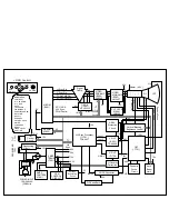
15. H & V Blanking and Brightness Control.
Blanking circuit eliminates retrace line by supplying
negative pulse to the G1 of the CRT. And Brightness
circuit is used for control of the screen brightness by
changing DC level of the G1.
16. Image Rotation (Tilt) Circuit.
This circuit corrects the tilt of the screen by supplying the
image rotation signal to the tilt coil which is attached near
the deflection yoke of the CRT.
17. Moire Rdduction Circuit
This circuit reduce interference between the periodical
display pattern and the CDT’s mask.
The positions of every other one dot video signal
beams(red, green, and blue beam) are shifted finely, thus
reducing interference.
18. OSD Circuit
This circuit is used for performing the OSD(On-Screen-
Display) function.
When a user selects the OSD Select/Adjustment control,
the adjustment status displays on the screen.
19. Video Pre-Amp Circuit.
This circuit amplifies the analog video signal from 0-0.7V
to 0-4V. It is operated by taking the clamp, R, G, B drive
and contrast signal from the Micom(IC401).
20. Video Output Amp Circuit.
This circuit amplifies the video signal which comes from
the video pre-amp circuit and amplified it to applied the
CRT cathode.
Содержание 177V
Страница 6: ...WIRING DIAGRAM 6 P501 P201 P405 P301 P302 G2 P702 P701 T1 P402 P902 S S Signal Cable AC Socket FBT ...
Страница 23: ...EXPLODED VIEW 23 8 B A 2 1 4 3 12 12 13 6 7 5 11 13 10 9 a b c M ENU SELECT ...
Страница 33: ... 35 D CIRCUIT BOARD 4 MAIN BOARD Solder Side 2 CONTROL BOARD Solder Side ...


