- 7 -
DISASSEMBLY
(a)
Back Cover
Cabinet
(b)
(c)
1
2
2
3
3
Tip
C
B
A
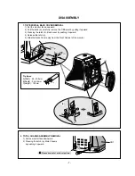
Tip Spec.
A(Width) : 5.0~15.0mm
B(Depth) : 0.6~0.9mm
C(Height) : 12.0mm
1. TILT/SWIVEL & BACK COVER REMOVAL
1) Set the monitor face downward.
2) Pull the latch (a), carefully remove the Tilt/Swivel by pulling it upward.
3) Pressing the latch (b), Back cover by pushing it upward.
4) Release the latch (c).
5) Slide the Back Cover away from the Front Cabinet of the monitor.
2. TOTAL CHASSIS ASSEMBLY REMOVAL
1) Set the monitor face downward.
2) Pressing the latch (a), Main Chassis
by pushing it upward.
(a)
(a’)
CDT
Please be careful, not to cut pattern.
Содержание 177V
Страница 6: ...WIRING DIAGRAM 6 P501 P201 P405 P301 P302 G2 P702 P701 T1 P402 P902 S S Signal Cable AC Socket FBT ...
Страница 23: ...EXPLODED VIEW 23 8 B A 2 1 4 3 12 12 13 6 7 5 11 13 10 9 a b c M ENU SELECT ...
Страница 33: ... 35 D CIRCUIT BOARD 4 MAIN BOARD Solder Side 2 CONTROL BOARD Solder Side ...


