background image

GA01201_1002 - 07/2005

27

Maintenance

5.6

Replacing the Shaft Seal

Required tools:

Allen keys 3 mm, 5 mm, 8 mm, flat-nose pliers, plastic hammer, shaft seal
driver, possibly puller for coupling.

The TRIVAC 4/8 B has two shaft seals; the outer one is subject to greater
wear. Oil marks under the coupling housing are signs of a damaged outer
shaft seal. 

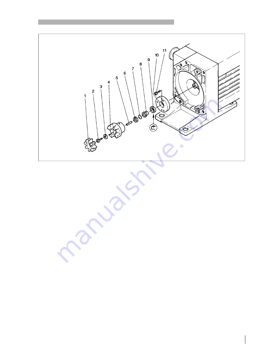
The outer shaft seal (12/9) can be replaced without removing or disassem-
bling the pump module.

Shutdown the pump.

Drain the oil (see Section 5.2) or place the pump on its front side.

Unscrew the four non-recessed hex. socket screws (11/7) and remove the
motor (11/6) together with the intermediate flange (11/8). 

Remove the gasket (11/1).

Remove the coupling element (12/1).

Remove the hex. socket screw (12/2) and the spring washer (12/3).

Pull off the coupling (12/4).

Remove the key (12/5).

Pull off the compression disc (12/6) and the O-ring (12/7).

Unscrew the hex. socket screws (12/11) and pull off the centering disk
(12/10) together with the bushing (12/8).

If the centering disk is stuck, screw the capscrews (12/11) into the jack-
screw holes in the centering disk.

Fig. 12  Exchanging the shaft seal

Key to Fig. 12

1 Coupling element
2 Hexagon socket screw
3 Spring washer
4 Coupling (one half)
5 Key
6 Compression disc
7 O-ring
8 Bushing
9 Shaft seal

10 Centering disk
11 Hexagon socket screws

Содержание TRIVAC B Series

Страница 1: ...vacuum Cat No 113 08 17 140 081 082 OPERATING INSTRUCTIONS GA01201_1002 TRIVAC B D 4 B D 8 B Rotary Vane Vacuum Pump...

Страница 2: ...allation 15 3 1 Placement 15 3 2 Connection to the System 16 3 3 Electrical Connections 17 3 4 Areas of Application 17 4 Operation 18 4 1 Start up 18 4 2 Operation 18 4 2 1 Pumping of Non Condensable...

Страница 3: ...and Reassembly of the Electric Motor 26 5 6 Replacing the Shaft Seal 27 5 7 Removing and Remounting the Pump Module 28 5 7 1 Removing the Pump Module 29 5 7 2 Remounting the Pump Module 29 5 8 Service...

Страница 4: ...which are subject to normal wear and which are contaminated due to the influence of oxygen in the air high temperatures or mechanical wear must be disposed of through the locally available waste oil...

Страница 5: ...d you have any questions relating to safety operation or maintenance of the equip ment please get in touch with your nearest Leybold Vacuum office The icon indicates procedures that must be strictly o...

Страница 6: ...to the vacuum Never operate the TRIVAC B without a connected intake line or blank flange at the intake port The location at which the TRIVAC B including its accessories is being operated should be suc...

Страница 7: ...e pump During this warming up phase the pump should be separated from the process by a blocking valve in the intake line for example In the case of wet processes we recommend the installation of liqui...

Страница 8: ...rosi ve media The drive motor of the TRIVAC B is directly flanged to the pump at the cou pling housing The pump and motor shafts are directly connected by a fle xible coupling The bearing points of th...

Страница 9: ...pump chamber The compressed gas in the pump chamber is ejected through the exhaust valve 2 10 The oil entrained in the gas is coarsely trapped in the internal demister 2 11 there the oil is also free...

Страница 10: ...ake pressures The vacuum is maintained by the TRIVAC B by an integrated hydropneu matic anti suckback valve 2 3 which is controlled via the oil pressure During operation of the TRIVAC B the control pi...

Страница 11: ...ipment supplied with the TRIVAC B pump includes Pump with motor including initial filling of N 62 or HE 200 oil 1 centering ring 1 centering ring with dirt trap 2 clamping rings DN 25 KF As protection...

Страница 12: ...with aluminium oxide 854 14 adsorption trap with cryo insert 854 17 Cold trap TK 4 8 188 20 Oil filter OF 4 25 101 91 Chemical filter CF 4 25 101 96 Adapter f r gas ballast port M 16 x 1 5 DN 16 KF 16...

Страница 13: ...allast Admissible ambient temperature C 12 40 Motor rating W 370 Nominal speed min 1 1500 Type of protection IP 54 Weight kg 18 7 21 2 Connections intake and exhaust side DN 16 KF 1 To DIN 28 400 and...

Страница 14: ...eyes provi ded on the pump for this purpose also use the recommended type of lifting device Caution Warning n m l c a b1 o h1 h h2 h3 b2 b Type DN a b b1 b2 c h h1 h2 h3 l m n o D 4 B Cat No 140 081...

Страница 15: ...he rubber feet act as vibration absorbers They must therefore not be compressed by screws When installing the TRIVAC B pump make sure that the connections and controls are readily accessible The site...

Страница 16: ...may occur in the pump this might damage the shaft seals and cause oil leaks The maximum pressure in the oil case must not exceed 1 5 bar absolute When pumping vapours it is advisable to install conden...

Страница 17: ...hase mains in Germany 16 amps for example The direction of rotation need not be checked as it is fixed The motor is protected against overloading by a thermal overload switch with automatic resetting...

Страница 18: ...il fill and oil drain openings must never be ope ned during operation The safety regulations which apply to the application in each case must be observed This applies to installation operation and dur...

Страница 19: ...to continue operating with the gas ballast valve open and the intake line closed until the oil is free of condensed vapours We strongly recommend operating the TRIVAC B in this mode for about 30 minut...

Страница 20: ...urther advice in these mat ters Drain the oil see Section 5 2 Add clean oil until the oil level is at the min mark see Section 5 2 and let the pump operate for some time Then drain the oil and add cle...

Страница 21: ...the pump This statement detailing the contamination is required to satisfy legal requi rements and for the protection of our employees Pumps which are not accompanied by a contamination statement will...

Страница 22: ...eck Normally the oil is clear and transparent If the oil darkens it should be changed b Chemical check The neutralisation number of N 62 oil is determined according to DIN 51558 If it exceeds 2 the oi...

Страница 23: ...erm storage of the pump If the oil becomes contaminated too quickly install a dust filter and or oil fil ter see Section 1 3 Contact us for more information in this matter Only change the oil after th...

Страница 24: ...mm The internal demister is spring mounted in a frame When it is clogged it rises periodically to reduce the pressure difference created The resultant noise at high intake pressures indicates that th...

Страница 25: ...buckles 3 Demister 4 Frame for demister 5 Hex socket screws 4 pcs 6 Slencing nozzle 7 Gasket Fig 11 Disassembly and reassembly of the electric motor Key to Fig 11 1 Gasket 2 Handle 3 Coupling 4 Thread...

Страница 26: ...the motor shaft Unscrew the hex socket screws 11 9 Remove the electric motor 11 6 and the adapter flange 11 5 in the case of the USA motors Clean all parts and check that they are in perfect conditio...

Страница 27: ...hex socket screws 11 7 and remove the motor 11 6 together with the intermediate flange 11 8 Remove the gasket 11 1 Remove the coupling element 12 1 Remove the hex socket screw 12 2 and the spring was...

Страница 28: ...12 11 Push the O ring 12 7 and the compression disc 12 6 onto the shaft Insert the key 12 5 Mount the pump half of the coupling 12 4 on the shaft Install the spring washer 12 3 and tighten the hex scr...

Страница 29: ...s tighten the tie rods Then remove the lock nuts Before mounting the pump module make sure that sealing disc 13 3 fits correctly in its bore ush the gasket 13 4 onto the tie rods 13 6 push the couplin...

Страница 30: ...ts and for the protection of our employees Pumps which are not accompanied by a contamination statement will be returned to the sender The pump must be packed in such a way that it will not be damaged...

Страница 31: ...utlets of the pump must be sealed with the shipping seals which are provided upon delivery The gas ballast switch must be set to the 0 position and if the pump is to be shelved for a longer period of...

Страница 32: ...h cleaning agent Replace the defective internal demister Dispose of the defective internal demister as special waste Cleaning agent according to national international specifications Observe the safet...

Страница 33: ...tly 3 1 4 2 3 observed Process gas is too hot Change the process Oil level is too low Add oil 5 1 Oil is unsuitable Change the oil 5 2 Oil cycle is obstructed Clean or repair the oil lines and channel...

Страница 34: ...GA01201_1002 07 2005 34 Troubleshooting 7 Spare Parts The spare parts for your vacuum pump are listed in the spare parts list enclosed with the product...

Страница 35: ...In case of any product changes made without our approval this declaration will be void Designation of the products Rotary vane vacuum pump dual stage Types TRIVAC D 4 D 8 B Cat No 140 081 140 082 The...

Страница 36: ...defined below is not permissible until it has been determined that the machine into which this incomplete machine is to be installed meets the regulations of the EEC Directive on Machinery Designation...

Страница 37: ...___________________________ __________________________________________________ B Condition of the equipment No Yes No Contamination No Yes 1 Has the equipment been used toxic 2 Drained Product service...

Страница 38: ...rtaboeuf Cedex Sales and Service Phone 33 1 69 82 48 00 Fax 33 1 69 07 57 38 sales france leybold com Leybold Vacuum France S A Valence Factory 640 Rue A Berg s B P 107 F 26501 Bourg l s Valence Cedex...

Отзывы: