background image

LEXUS 

GX470 

2007 -  

XM SATELLITE RADIO TUNER 

Procedure

Page 8 of 30 pages 

Issue: D  11/18/08 

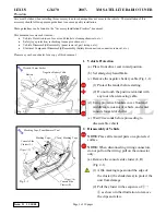
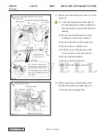
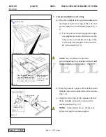
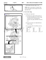
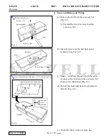
(5) Tilt seat back.  Do not remove the seat. 

NOTE:

Ensure there is enough slack  in wire 

harness when the seat is tilted back. 

(6) If enough slack is not obtained, Push the 

seat over towards the rear and remove the 

seat harness connectors and clamp (Fig. 

2-13).

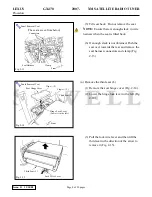
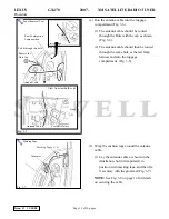
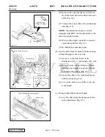
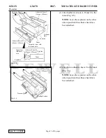
(n) Remove the third seat (L). 

(1) Remove the seat hinge cover (Fig. 2-14). 

(2) Lower the hinge lock lever to the left (Fig. 

2-14).

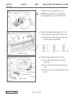
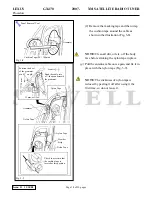
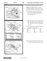
(3) Pull the lock wire lever and then lift the 

third seat in the direction of the arrow to 

remove it (Fig. 2-15). 

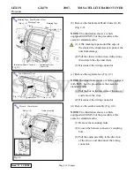
Fig. 2-13 

             Connectors 

Front

Panel Removal Tool 

Clamp

Seat Harness 

ާ

The seat as seen from below

ި

Panel Removal Tool 

Fig. 2-14 

Seat Hinge Cover 

Clips (

˜

2)

Front

Third Seat (L)

Hinge Lock Lever 
(Lower it to the left) 

Claws (

˜

2)

Fig. 2-15 

Lock Wire Lever 

Third Seat (L) 

Содержание 86100-0W230

Страница 1: ...flicts iPod Interface Sirius Satellite Radio Recommended Tools Personal Vehicle Protection Notes Vehicle Protection Clean Cloths Part Boxes Special Tools Notes None Installation Tools Notes Panel Clip...

Страница 2: ...e One piece is used for the half cutting it refer to Fig 4 4 Fig 6 12 Item Parts Name Parts No Qty 1 Wire To Radio Installation 1 82372 0W110 1 2 Ground Cable 1 3 Tie Wrap 14 4 Cushion Tape 50mm 100mm...

Страница 3: ...seat in mid position b Set emergency hand brake c Remove the negative battery cable Fig 1 1 1 Protect the fender before starting 2 Do not touch the positive terminal with any tool when removing cable...

Страница 4: ...ipped with EMV but the procedure is the same for standard audio 1 Pull the box in the direction of the arrow and remove the clips 2 Disconnect the wiring connector d Remove the audio assembly Fig 2 4...

Страница 5: ...ove the Nut 2 Pull the cover in the direction of the arrow and remove the clips h Remove the instrument panel under cover L Fig 2 7 1 Remove the screw 2 Pull the cover in the direction of the arrow an...

Страница 6: ...law 6 Remove the hood opener 7 Remove the fuel lid opener 8 Disconnect the wiring connector j Remove the harness guard bracket at the bottom of the steering column Fig 2 9 1 Remove the mounting bolts...

Страница 7: ...ten them to 32 0 N m 24 lbf ft 3 Remove the seat leg covers on the front side Fig 2 12 4 Remove the front mounting bolts Fig 2 12 NOTE When putting the mounting bolts back tighten them to 32 0 N m 24...

Страница 8: ...s connectors and clamp Fig 2 13 n Remove the third seat L 1 Remove the seat hinge cover Fig 2 14 2 Lower the hinge lock lever to the left Fig 2 14 3 Pull the lock wire lever and then lift the third se...

Страница 9: ...he clip and claw p Pull back the luggage carpet Fig 2 18 1 Loosen the bolt and remove the front rope hook 2 Loosen the bolt and remove the rear rope hook 3 Pull back the carpet in the direction of the...

Страница 10: ...the front weather strip 6 Pull the trim in the direction of the arrow and remove the clip and claw s Remove the rear combination lamp L Fig 2 20 NOTE Cover the perimeter of the tail lamp assembly prio...

Страница 11: ...g from antenna terminal until antenna installation is complete Fig 3 11 b Peel the protective paper off the double sided adhesive tape on the underside of the antenna Fig 3 2 c Align the front edge of...

Страница 12: ...ar combination lamp position Fig 3 4 3 5 NOTE The weather strip cannot be reused so do not remove it completely When inserting the cable beneath the weather strip peel back the weather strip as shown...

Страница 13: ...gage compartment Fig 3 6 f Wrap the cushion tape around the antenna cable 1 Lay the antenna cable as shown in the illustration hold it temporarily in position with masking tape and then fix it securel...

Страница 14: ...na cable once again and fix it in place with the nylon tape Fig 3 9 NOTE The stickiness of nylon tape is reduced by peeling it off after using it the first time so do not reuse it Fig 3 8 Panel Remova...

Страница 15: ...2 If the lock plate of the housing is pushed in pull it out Fig 3 12 NOTE This step is not required if the lock plate is already pulled out 3 Push the terminal into the housing Fig 3 13 Antenna Cable...

Страница 16: ...ner cable from the position at the bottom right hand side of the steering column as shown in the illustration through to the audio attachment area Fig 4 1 2 Fasten the cable to the indicated harness w...

Страница 17: ...e bottom of the steering column through to the cowl side 1 Secure it to the duct shown in the illustration with cushion tape Fig 4 4 2 Using scissors cut one 50mm x 100mm cushion tape in half to make...

Страница 18: ...t the wiring connector 24P 6P 10P 10P from the amp and interpose the tuner cable 24P 6P before reconnecting Fig 4 7 3 Wrap cushion tape around the connector connection position Fig 4 8 4 Reconnect the...

Страница 19: ...tie wrap length f Wiring around the rear wheel house luggage side 1 Pull the tuner cable along the harness shown in the illustration Figs 4 11 4 12 NOTE The cable should not be secured in place at thi...

Страница 20: ...bove the ground screw location where the vehicle harness branches The wire harness should then pass between the oil inlet and steel plate to the tuner attachment area c Gather the ground cable the tun...

Страница 21: ...tie wraps Fig 5 6 i Secure the excess tuner cable to the location shown in the illustration with the tie wraps Fig 5 6 j Use a side cutter to cut off the excess tie wrap length Fig 5 4 Side Cutter Tie...

Страница 22: ...Make a round hole through which the cable can pass at the location on the accessory box shown in the illustration Fig 6 3 d De burr the hole and attach the grommet to the hole Fig 6 4 e Attach the tun...

Страница 23: ...tach two adhesive sheets C to the tuner Fig 6 6 NOTE Leave the separator on the other side in position when these sheets have been attached Fig 6 5 Align the screw with the round hole Adhesive Sheet A...

Страница 24: ...Sheet A Peel the separator from adhesive sheet A Separator With the separator still in place bring adhesive sheet B into contact with the bottom and then slide it along until it comes into contact wit...

Страница 25: ...h the hole on the accessory box Fig 6 9 i Attach the ground cable to the tuner Fig 6 9 j Attach the accessory box to the luggage side lower trim L and then connect the cables 1 Peel the separator from...

Страница 26: ...tion with cushion tape Fig 6 12 NOTE Use cushion from step 4 b as shown Fig 6 12 m Stick adhesive sheet D onto the tuner cover Fig 6 13 Fig 6 11 Tuner Cable Antenna Cable Press it onto the luggage sid...

Страница 27: ...tuner cover to the tuner and accessory box Fig 6 15 Fig 6 14 Tuner Cover Adhesive Sheet C Insert adhesive sheet D with the separator in place Fig 6 15 With the separator still in place bring adhesive...

Страница 28: ...er Seat Specified Tightening Torque 32 N M 24 lbf ft 2 3rd Row Seat Specified Tightening Torque 37 N M 24 lbf ft 3 2nd and 3rd Row Seat Belts Specified Tightening Torque 42 N M 31 lbf ft c Clean up an...

Страница 29: ...on System if equipped Foot Light Mirror Switch RSCA Switch 2nd Start Switch Tire Pressure Switch Hood Opener Fuel Lid Opener Power Seat driver s seat Third Rear Seat Operation 2nd Row Driver Side Seat...

Страница 30: ...Left Rear Turn Signal Brake Light Reverse Light Tail Light After the battery cable is reconnected the functional components of the car need to re initialize Initialize them with reference to RM03F0U i...

Отзывы: