TPS wiper 386
TPS wiper mechanism 384
transfer module 388
transfer module guide rail 390
tray rail 421
waste toner bottle idler gear 378
reports
device settings 281
installed licenses 282
restoring
configuration file 300
license file 300
ribbon cables 302
S
scan quality troubleshooting
ADF skew 67
dark image 64
media damage (using the ADF) 69
spots 66
vertical lines 65
scanner diagnostics
feed test 286
motor tests 289
multifeed calibration 289
scanner calibration reset 289
sensor tests 286
scanner glass
cleaning 482
scanner manual registration 307
scheduled maintenance 480
selecting a location for the printer 522
selecting paper 27
service checks troubleshooting
8yy service error messages 238
900 service error messages 223
91y service error messages 224
938 service error messages 224
95y service error messages 224
96y service error messages 225
97y service error messages 226
980–984 service error messages 227
99y service error messages 227
network service check 265
usb service check 269
service engineer (SE) menu
accessing 291
fax SE 292
general SE 291
network SE 291
scan SE 293
spots 66
storing
supply reset
supported paper sizes 29
supported paper types 31
supported paper weights 31
symptoms
T
tips
card stock 28
labels, paper 28
on using envelopes 27
tips on using envelopes 27
tools, required 32
trays
installing 525
troubleshooting
initial check 35
scan/fax/copy symptoms 240
troubleshooting, print quality
adf duplex service check 247
adf feed errors service check 245
ADF open service check 161
ADF paper jam service check 158
ADF top cover open service check 162
ADF tray empty service check 163
background or gray background 38
black or blank page copy service check 241
blank or white pages 39
blurred print or color misalignment 42
dark print 54
fax reception service check 249
fax transmission service check 251
flatbed home position service check 242
flatbed legal
‑
flatbed motor service check 242
gapping or half color page 41
ghost images 48
horizontal colored lines or banding 43
image void process direction 53
image void scan direction 51
light print 59
modem/fax card service check 248
mottled print and dots 45
random marks 59
scanner communication failure service check 239
scanner disabled error service check 238
7528
Index
561
Содержание XC4150
Страница 34: ...7528 34 ...
Страница 276: ...7528 276 ...
Страница 294: ...Scan SE Scanner Info 7528 Service menus 294 ...
Страница 310: ...3 Disconnect the front door straps C C 4 Remove the screw C securing the ground cables D 7528 Repair information 310 ...
Страница 317: ...3 Remove the screw B from the lower left side of the cover B 7528 Repair information 317 ...
Страница 320: ...3 Remove the three screws A 7528 Repair information 320 ...
Страница 325: ...4 Remove the six screws B from the bracket and then remove the bracket B 7528 Repair information 325 ...
Страница 327: ...3 Remove the E clip B 4 Remove the E clip C 7528 Repair information 327 ...
Страница 331: ...Top frame cover removal 1 Open the front cover and then raise the diverter 7528 Repair information 331 ...
Страница 352: ...3 Disconnect the motor cable A 4 Remove the three screws B and then remove the motor 7528 Repair information 352 ...
Страница 354: ...4 Disconnect the fuser fan cable A from the controller board A 5 Remove the two screws B 7528 Repair information 354 ...
Страница 358: ...5 Remove the two screws D from under the gear box 7528 Repair information 358 ...
Страница 360: ...3 Disconnect the cable A from the LVPS 7528 Repair information 360 ...
Страница 361: ...4 Remove the seven screws B 5 Disconnect the two cables C and then remove the LVPS 7528 Repair information 361 ...
Страница 364: ...6 Disconnect the black only retract motor cable A 7 Remove the two screws B 7528 Repair information 364 ...
Страница 367: ...6 Pull the mounting assembly away from the printer 7 Disconnect the sensor cable B 7528 Repair information 367 ...
Страница 370: ...3 Disconnect the motor cable A A 7528 Repair information 370 ...
Страница 371: ...4 Remove the four screws B and then remove the motor B 7528 Repair information 371 ...
Страница 374: ...4 Disconnect the cable B 5 Remove the screw C securing the HVPS C 7528 Repair information 374 ...
Страница 377: ...5 Pull the sensor A out of the printer 6 Disconnect the sensor cable B to remove the sensor 7528 Repair information 377 ...
Страница 389: ...5 Remove the imaging kit 1 2 3 6 Open the front cover 7 Remove the transfer module 1 2 7528 Repair information 389 ...
Страница 398: ...9 Remove the bracket D and then unhook the spring E 10 Remove the spacer F 7528 Repair information 398 ...
Страница 400: ...14 Remove the clip M and then remove the spacer 7528 Repair information 400 ...
Страница 403: ...7528 Repair information 403 ...
Страница 414: ...5 Remove the screw C from the printhead 7528 Repair information 414 ...
Страница 417: ...7 Remove the E clip A and then remove the gear 8 Remove the E clip B from inside the frame 7528 Repair information 417 ...
Страница 424: ...3 Remove the three screws A securing the isolation unit 4 Remove the biasing screw B 7528 Repair information 424 ...
Страница 429: ...8 Route the ADF cable through the flatbed 9 Remove the ADF 7528 Repair information 429 ...
Страница 437: ...7 Disconnect the two cables B on the controller board 7528 Repair information 437 ...
Страница 439: ...10 Remove the cotter pin D on the left side of the flatbed 11 Slide out the pins to remove 7528 Repair information 439 ...
Страница 443: ...5 Remove the screw D and then remove the scanner tilt D 7528 Repair information 443 ...
Страница 446: ...5 Remove the two screws B B 6 Disconnect the cable C C 7 Remove the motor 7528 Repair information 446 ...
Страница 450: ...3 Release the latch A and then remove the sensor cover A 4 Release the two latches B B 7528 Repair information 450 ...
Страница 478: ...7528 478 ...
Страница 485: ...7528 485 ...
Страница 487: ...Assembly 1 Covers 1 2 4 6 7 8 9 1 14 10 3 5 13 13 11 11 12 7528 Parts catalog 487 ...
Страница 489: ...Assembly 2 Covers 2 14 7528 Parts catalog 489 ...
Страница 491: ...Assembly 3 Control panel 5 4 3 2 1 7528 Parts catalog 491 ...
Страница 493: ...Assembly 4 ADF and flatbed 1 3 11 10 4 9 5 6 7 8 2 7528 Parts catalog 493 ...
Страница 495: ...Assembly 5 Fuser 1 7528 Parts catalog 495 ...
Страница 497: ...Assembly 6 Transfer module 1 2 7528 Parts catalog 497 ...
Страница 499: ...Assembly 7 Paper feed 8 2 1 2 4 7 3 5 5 6 7528 Parts catalog 499 ...
Страница 501: ...Assembly 8 Paper path 1 8 6 2 3 1 10 5 7 9 4 7528 Parts catalog 501 ...
Страница 503: ...Assembly 9 Paper path 2 1 4 2 5 10 3 6 9 7 8 7528 Parts catalog 503 ...
Страница 505: ...Assembly 10 Duplex 9 8 3 3 7 6 1 1 2 4 5 7528 Parts catalog 505 ...
Страница 507: ...Assembly 11 Electrical 16 2 3 4 5 7 8 9 11 12 13 15 6 1 14 10 7528 Parts catalog 507 ...
Страница 510: ...7528 Parts catalog 510 ...
Страница 511: ...Assembly 12 550 sheet tray option 1 2 1 7528 Parts catalog 511 ...
Страница 513: ...Assembly 13 550 sheet tray option 2 1 2 3 4 12 11 6 13 5 9 10 7 8 7528 Parts catalog 513 ...
Страница 515: ...Assembly 14 Adjustable stand 2 2 3 3 1 7528 Parts catalog 515 ...
Страница 518: ...7528 Parts catalog 518 ...
Страница 520: ...7528 520 ...
Страница 524: ...Storage temperature and relative humidity 10 to 40 C 14 to 104 F 8 to 80 RH 7528 Appendix A Printer specifications 524 ...
Страница 527: ...3 Apply the changes 7528 Appendix B Options and features 527 ...
Страница 528: ...7528 528 ...
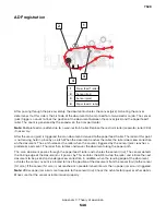
Страница 533: ... Description 1 Transfer belt 2 Sensor input 3 Aligner roller 4 Transfer roller 7528 Appendix C Theory of operation 533 ...
Страница 554: ...7528 554 ...
Страница 568: ...7528 Part number index 568 ...
Страница 574: ...7528 Part name index 574 ...


