


Diagnostic information
CAUTION—SHOCK HAZARD:
To avoid the risk of electrical shock and to prevent damage to the printer,
remove the power cord from the electrical outlet before you connect or disconnect any cable or
electronic card or assembly for personal safety and to prevent damage to the printer. Disconnect any
connections between the printer and computers or peripherals.
CAUTION—POTENTIAL INJURY:
The printer weight is greater than 18 kg (40 lb) and requires two or
more trained personnel to lift it safely. Always use the hand holds on the sides of the printer. Make sure
that your fingers are not under the printer when you lift or set the printer down.
CAUTION—HOT SURFACE:
The inside of the printer might be hot. To reduce the risk of injury from a hot
component, allow the surface to cool before touching.
Troubleshooting overview
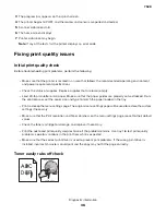
Performing the initial troubleshooting check
•
With the power cord unplugged from the electrical outlet, check if the cord is free from breakage, short
circuits, disconnected wires, or incorrect connections.
•
Make sure that the printer is properly grounded.
•
Make sure that the power supply line voltage is within 10% of the rated line voltage.
•
Make sure that the printer is securely installed on a level surface in a well
‑
ventilated area.
•
Make sure that the temperature and relative humidity are within the specifications. See
•
Avoid locations that:
–
Generate ammonia gas
–
Are exposed to direct sunlight
–
Are near open flames
–
Are dusty
•
Make sure that the recommended paper for this printer is used.
•
Do a test print with paper from a newly opened package, and then check the result.
Power
‑
on reset (POR) sequence
When you turn on the printer, it performs a POR sequence.
Check for the correct POR function of the printer by observing the following:
1
The initial boot screen appears.
2
The splash screen appears.
7528
Diagnostic information
35
Содержание XC4150
Страница 34: ...7528 34 ...
Страница 276: ...7528 276 ...
Страница 294: ...Scan SE Scanner Info 7528 Service menus 294 ...
Страница 310: ...3 Disconnect the front door straps C C 4 Remove the screw C securing the ground cables D 7528 Repair information 310 ...
Страница 317: ...3 Remove the screw B from the lower left side of the cover B 7528 Repair information 317 ...
Страница 320: ...3 Remove the three screws A 7528 Repair information 320 ...
Страница 325: ...4 Remove the six screws B from the bracket and then remove the bracket B 7528 Repair information 325 ...
Страница 327: ...3 Remove the E clip B 4 Remove the E clip C 7528 Repair information 327 ...
Страница 331: ...Top frame cover removal 1 Open the front cover and then raise the diverter 7528 Repair information 331 ...
Страница 352: ...3 Disconnect the motor cable A 4 Remove the three screws B and then remove the motor 7528 Repair information 352 ...
Страница 354: ...4 Disconnect the fuser fan cable A from the controller board A 5 Remove the two screws B 7528 Repair information 354 ...
Страница 358: ...5 Remove the two screws D from under the gear box 7528 Repair information 358 ...
Страница 360: ...3 Disconnect the cable A from the LVPS 7528 Repair information 360 ...
Страница 361: ...4 Remove the seven screws B 5 Disconnect the two cables C and then remove the LVPS 7528 Repair information 361 ...
Страница 364: ...6 Disconnect the black only retract motor cable A 7 Remove the two screws B 7528 Repair information 364 ...
Страница 367: ...6 Pull the mounting assembly away from the printer 7 Disconnect the sensor cable B 7528 Repair information 367 ...
Страница 370: ...3 Disconnect the motor cable A A 7528 Repair information 370 ...
Страница 371: ...4 Remove the four screws B and then remove the motor B 7528 Repair information 371 ...
Страница 374: ...4 Disconnect the cable B 5 Remove the screw C securing the HVPS C 7528 Repair information 374 ...
Страница 377: ...5 Pull the sensor A out of the printer 6 Disconnect the sensor cable B to remove the sensor 7528 Repair information 377 ...
Страница 389: ...5 Remove the imaging kit 1 2 3 6 Open the front cover 7 Remove the transfer module 1 2 7528 Repair information 389 ...
Страница 398: ...9 Remove the bracket D and then unhook the spring E 10 Remove the spacer F 7528 Repair information 398 ...
Страница 400: ...14 Remove the clip M and then remove the spacer 7528 Repair information 400 ...
Страница 403: ...7528 Repair information 403 ...
Страница 414: ...5 Remove the screw C from the printhead 7528 Repair information 414 ...
Страница 417: ...7 Remove the E clip A and then remove the gear 8 Remove the E clip B from inside the frame 7528 Repair information 417 ...
Страница 424: ...3 Remove the three screws A securing the isolation unit 4 Remove the biasing screw B 7528 Repair information 424 ...
Страница 429: ...8 Route the ADF cable through the flatbed 9 Remove the ADF 7528 Repair information 429 ...
Страница 437: ...7 Disconnect the two cables B on the controller board 7528 Repair information 437 ...
Страница 439: ...10 Remove the cotter pin D on the left side of the flatbed 11 Slide out the pins to remove 7528 Repair information 439 ...
Страница 443: ...5 Remove the screw D and then remove the scanner tilt D 7528 Repair information 443 ...
Страница 446: ...5 Remove the two screws B B 6 Disconnect the cable C C 7 Remove the motor 7528 Repair information 446 ...
Страница 450: ...3 Release the latch A and then remove the sensor cover A 4 Release the two latches B B 7528 Repair information 450 ...
Страница 478: ...7528 478 ...
Страница 485: ...7528 485 ...
Страница 487: ...Assembly 1 Covers 1 2 4 6 7 8 9 1 14 10 3 5 13 13 11 11 12 7528 Parts catalog 487 ...
Страница 489: ...Assembly 2 Covers 2 14 7528 Parts catalog 489 ...
Страница 491: ...Assembly 3 Control panel 5 4 3 2 1 7528 Parts catalog 491 ...
Страница 493: ...Assembly 4 ADF and flatbed 1 3 11 10 4 9 5 6 7 8 2 7528 Parts catalog 493 ...
Страница 495: ...Assembly 5 Fuser 1 7528 Parts catalog 495 ...
Страница 497: ...Assembly 6 Transfer module 1 2 7528 Parts catalog 497 ...
Страница 499: ...Assembly 7 Paper feed 8 2 1 2 4 7 3 5 5 6 7528 Parts catalog 499 ...
Страница 501: ...Assembly 8 Paper path 1 8 6 2 3 1 10 5 7 9 4 7528 Parts catalog 501 ...
Страница 503: ...Assembly 9 Paper path 2 1 4 2 5 10 3 6 9 7 8 7528 Parts catalog 503 ...
Страница 505: ...Assembly 10 Duplex 9 8 3 3 7 6 1 1 2 4 5 7528 Parts catalog 505 ...
Страница 507: ...Assembly 11 Electrical 16 2 3 4 5 7 8 9 11 12 13 15 6 1 14 10 7528 Parts catalog 507 ...
Страница 510: ...7528 Parts catalog 510 ...
Страница 511: ...Assembly 12 550 sheet tray option 1 2 1 7528 Parts catalog 511 ...
Страница 513: ...Assembly 13 550 sheet tray option 2 1 2 3 4 12 11 6 13 5 9 10 7 8 7528 Parts catalog 513 ...
Страница 515: ...Assembly 14 Adjustable stand 2 2 3 3 1 7528 Parts catalog 515 ...
Страница 518: ...7528 Parts catalog 518 ...
Страница 520: ...7528 520 ...
Страница 524: ...Storage temperature and relative humidity 10 to 40 C 14 to 104 F 8 to 80 RH 7528 Appendix A Printer specifications 524 ...
Страница 527: ...3 Apply the changes 7528 Appendix B Options and features 527 ...
Страница 528: ...7528 528 ...
Страница 533: ... Description 1 Transfer belt 2 Sensor input 3 Aligner roller 4 Transfer roller 7528 Appendix C Theory of operation 533 ...
Страница 554: ...7528 554 ...
Страница 568: ...7528 Part number index 568 ...
Страница 574: ...7528 Part name index 574 ...


