5
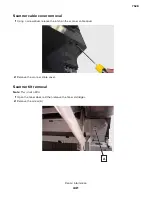
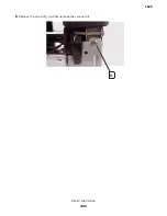
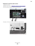
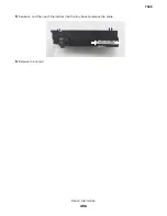
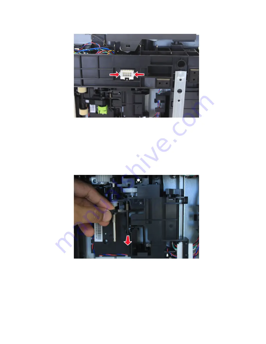
Squeeze, and then push the latches into the tray base to release the cable.
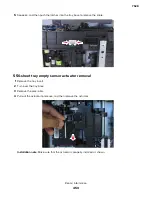
550-sheet tray empty sensor actuator removal
1
Remove the tray insert.
2
Turn over the tray base.
3
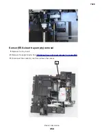
Remove the pick roller.
4
Pull out the actuator to release, and then remove the actuator.
Installation note:
Make sure that the actuator is properly installed as shown.
7528
Repair information
453
Содержание XC4150
Страница 34: ...7528 34 ...
Страница 276: ...7528 276 ...
Страница 294: ...Scan SE Scanner Info 7528 Service menus 294 ...
Страница 310: ...3 Disconnect the front door straps C C 4 Remove the screw C securing the ground cables D 7528 Repair information 310 ...
Страница 317: ...3 Remove the screw B from the lower left side of the cover B 7528 Repair information 317 ...
Страница 320: ...3 Remove the three screws A 7528 Repair information 320 ...
Страница 325: ...4 Remove the six screws B from the bracket and then remove the bracket B 7528 Repair information 325 ...
Страница 327: ...3 Remove the E clip B 4 Remove the E clip C 7528 Repair information 327 ...
Страница 331: ...Top frame cover removal 1 Open the front cover and then raise the diverter 7528 Repair information 331 ...
Страница 352: ...3 Disconnect the motor cable A 4 Remove the three screws B and then remove the motor 7528 Repair information 352 ...
Страница 354: ...4 Disconnect the fuser fan cable A from the controller board A 5 Remove the two screws B 7528 Repair information 354 ...
Страница 358: ...5 Remove the two screws D from under the gear box 7528 Repair information 358 ...
Страница 360: ...3 Disconnect the cable A from the LVPS 7528 Repair information 360 ...
Страница 361: ...4 Remove the seven screws B 5 Disconnect the two cables C and then remove the LVPS 7528 Repair information 361 ...
Страница 364: ...6 Disconnect the black only retract motor cable A 7 Remove the two screws B 7528 Repair information 364 ...
Страница 367: ...6 Pull the mounting assembly away from the printer 7 Disconnect the sensor cable B 7528 Repair information 367 ...
Страница 370: ...3 Disconnect the motor cable A A 7528 Repair information 370 ...
Страница 371: ...4 Remove the four screws B and then remove the motor B 7528 Repair information 371 ...
Страница 374: ...4 Disconnect the cable B 5 Remove the screw C securing the HVPS C 7528 Repair information 374 ...
Страница 377: ...5 Pull the sensor A out of the printer 6 Disconnect the sensor cable B to remove the sensor 7528 Repair information 377 ...
Страница 389: ...5 Remove the imaging kit 1 2 3 6 Open the front cover 7 Remove the transfer module 1 2 7528 Repair information 389 ...
Страница 398: ...9 Remove the bracket D and then unhook the spring E 10 Remove the spacer F 7528 Repair information 398 ...
Страница 400: ...14 Remove the clip M and then remove the spacer 7528 Repair information 400 ...
Страница 403: ...7528 Repair information 403 ...
Страница 414: ...5 Remove the screw C from the printhead 7528 Repair information 414 ...
Страница 417: ...7 Remove the E clip A and then remove the gear 8 Remove the E clip B from inside the frame 7528 Repair information 417 ...
Страница 424: ...3 Remove the three screws A securing the isolation unit 4 Remove the biasing screw B 7528 Repair information 424 ...
Страница 429: ...8 Route the ADF cable through the flatbed 9 Remove the ADF 7528 Repair information 429 ...
Страница 437: ...7 Disconnect the two cables B on the controller board 7528 Repair information 437 ...
Страница 439: ...10 Remove the cotter pin D on the left side of the flatbed 11 Slide out the pins to remove 7528 Repair information 439 ...
Страница 443: ...5 Remove the screw D and then remove the scanner tilt D 7528 Repair information 443 ...
Страница 446: ...5 Remove the two screws B B 6 Disconnect the cable C C 7 Remove the motor 7528 Repair information 446 ...
Страница 450: ...3 Release the latch A and then remove the sensor cover A 4 Release the two latches B B 7528 Repair information 450 ...
Страница 478: ...7528 478 ...
Страница 485: ...7528 485 ...
Страница 487: ...Assembly 1 Covers 1 2 4 6 7 8 9 1 14 10 3 5 13 13 11 11 12 7528 Parts catalog 487 ...
Страница 489: ...Assembly 2 Covers 2 14 7528 Parts catalog 489 ...
Страница 491: ...Assembly 3 Control panel 5 4 3 2 1 7528 Parts catalog 491 ...
Страница 493: ...Assembly 4 ADF and flatbed 1 3 11 10 4 9 5 6 7 8 2 7528 Parts catalog 493 ...
Страница 495: ...Assembly 5 Fuser 1 7528 Parts catalog 495 ...
Страница 497: ...Assembly 6 Transfer module 1 2 7528 Parts catalog 497 ...
Страница 499: ...Assembly 7 Paper feed 8 2 1 2 4 7 3 5 5 6 7528 Parts catalog 499 ...
Страница 501: ...Assembly 8 Paper path 1 8 6 2 3 1 10 5 7 9 4 7528 Parts catalog 501 ...
Страница 503: ...Assembly 9 Paper path 2 1 4 2 5 10 3 6 9 7 8 7528 Parts catalog 503 ...
Страница 505: ...Assembly 10 Duplex 9 8 3 3 7 6 1 1 2 4 5 7528 Parts catalog 505 ...
Страница 507: ...Assembly 11 Electrical 16 2 3 4 5 7 8 9 11 12 13 15 6 1 14 10 7528 Parts catalog 507 ...
Страница 510: ...7528 Parts catalog 510 ...
Страница 511: ...Assembly 12 550 sheet tray option 1 2 1 7528 Parts catalog 511 ...
Страница 513: ...Assembly 13 550 sheet tray option 2 1 2 3 4 12 11 6 13 5 9 10 7 8 7528 Parts catalog 513 ...
Страница 515: ...Assembly 14 Adjustable stand 2 2 3 3 1 7528 Parts catalog 515 ...
Страница 518: ...7528 Parts catalog 518 ...
Страница 520: ...7528 520 ...
Страница 524: ...Storage temperature and relative humidity 10 to 40 C 14 to 104 F 8 to 80 RH 7528 Appendix A Printer specifications 524 ...
Страница 527: ...3 Apply the changes 7528 Appendix B Options and features 527 ...
Страница 528: ...7528 528 ...
Страница 533: ... Description 1 Transfer belt 2 Sensor input 3 Aligner roller 4 Transfer roller 7528 Appendix C Theory of operation 533 ...
Страница 554: ...7528 554 ...
Страница 568: ...7528 Part number index 568 ...
Страница 574: ...7528 Part name index 574 ...

