Index
A
acronyms 555
adding hardware options
adding internal options
additional input tray diagnostics
motor tests 290
sensor tests 290
ADF duplex 550
ADF paper path 545
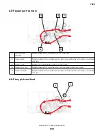
ADF paper path sensors 546
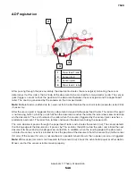
ADF registration 548
ADF scan and exit 549
ADF sensors
ADF separation 547
ADF skew check
ADF tray pick and feed 546
adjustment
ADF registration 307
flatbed registration 308
printhead 303
registration alignment 305
advanced print quality samples 282
available internal options 525
avoiding jams 27
avoiding paper jams 70
C
card stock
cleaning
exterior of the printer 482
interior of the printer 482
main tray duplex turnaround 484
printhead lenses 483
scanner glass 482
cleaning the printer 482
color theory 551
configuration menu
scanner manual registration 307
connectors
controller board 458
LVPS controller board 473
control panel
controller board, removing with 296
using 277
controller board
control panel, removing with 296
controller board, restoring configuration 297
D
dark image quality 64
data security notice 31, 295
diagnostics menu
accessing 280
feed test 286
multifeed calibration 289
scanner calibration reset 289
E
electrophotographic process 537
electrostatic
‑
sensitive parts 296
embedded solutions 302
emission notices 523
envelopes
tips on using 27
EP process 537
error codes
100 error messages 181
102 error messages 182
110 error messages 183
120 error messages 183
121 error messages 184
126 and 127 error messages 186
128 error message 186
142 error messages 186
144 error messages 187
145 error messages 187
147 error messages 187
149 error messages 188
150 and 160 error messages 188
151 error messages 189
153 error messages 190
161 and 162 error messages 189
163 and 164 error messages 190
166–168 error messages 191
17y error messages 191
200 paper jam messages 78
201 paper jam messages 84
202 paper jam messages 85
203 paper jam messages 93
211 paper jam messages 94
221 paper jam messages 95
7528
Index
557
Содержание XC4150
Страница 34: ...7528 34 ...
Страница 276: ...7528 276 ...
Страница 294: ...Scan SE Scanner Info 7528 Service menus 294 ...
Страница 310: ...3 Disconnect the front door straps C C 4 Remove the screw C securing the ground cables D 7528 Repair information 310 ...
Страница 317: ...3 Remove the screw B from the lower left side of the cover B 7528 Repair information 317 ...
Страница 320: ...3 Remove the three screws A 7528 Repair information 320 ...
Страница 325: ...4 Remove the six screws B from the bracket and then remove the bracket B 7528 Repair information 325 ...
Страница 327: ...3 Remove the E clip B 4 Remove the E clip C 7528 Repair information 327 ...
Страница 331: ...Top frame cover removal 1 Open the front cover and then raise the diverter 7528 Repair information 331 ...
Страница 352: ...3 Disconnect the motor cable A 4 Remove the three screws B and then remove the motor 7528 Repair information 352 ...
Страница 354: ...4 Disconnect the fuser fan cable A from the controller board A 5 Remove the two screws B 7528 Repair information 354 ...
Страница 358: ...5 Remove the two screws D from under the gear box 7528 Repair information 358 ...
Страница 360: ...3 Disconnect the cable A from the LVPS 7528 Repair information 360 ...
Страница 361: ...4 Remove the seven screws B 5 Disconnect the two cables C and then remove the LVPS 7528 Repair information 361 ...
Страница 364: ...6 Disconnect the black only retract motor cable A 7 Remove the two screws B 7528 Repair information 364 ...
Страница 367: ...6 Pull the mounting assembly away from the printer 7 Disconnect the sensor cable B 7528 Repair information 367 ...
Страница 370: ...3 Disconnect the motor cable A A 7528 Repair information 370 ...
Страница 371: ...4 Remove the four screws B and then remove the motor B 7528 Repair information 371 ...
Страница 374: ...4 Disconnect the cable B 5 Remove the screw C securing the HVPS C 7528 Repair information 374 ...
Страница 377: ...5 Pull the sensor A out of the printer 6 Disconnect the sensor cable B to remove the sensor 7528 Repair information 377 ...
Страница 389: ...5 Remove the imaging kit 1 2 3 6 Open the front cover 7 Remove the transfer module 1 2 7528 Repair information 389 ...
Страница 398: ...9 Remove the bracket D and then unhook the spring E 10 Remove the spacer F 7528 Repair information 398 ...
Страница 400: ...14 Remove the clip M and then remove the spacer 7528 Repair information 400 ...
Страница 403: ...7528 Repair information 403 ...
Страница 414: ...5 Remove the screw C from the printhead 7528 Repair information 414 ...
Страница 417: ...7 Remove the E clip A and then remove the gear 8 Remove the E clip B from inside the frame 7528 Repair information 417 ...
Страница 424: ...3 Remove the three screws A securing the isolation unit 4 Remove the biasing screw B 7528 Repair information 424 ...
Страница 429: ...8 Route the ADF cable through the flatbed 9 Remove the ADF 7528 Repair information 429 ...
Страница 437: ...7 Disconnect the two cables B on the controller board 7528 Repair information 437 ...
Страница 439: ...10 Remove the cotter pin D on the left side of the flatbed 11 Slide out the pins to remove 7528 Repair information 439 ...
Страница 443: ...5 Remove the screw D and then remove the scanner tilt D 7528 Repair information 443 ...
Страница 446: ...5 Remove the two screws B B 6 Disconnect the cable C C 7 Remove the motor 7528 Repair information 446 ...
Страница 450: ...3 Release the latch A and then remove the sensor cover A 4 Release the two latches B B 7528 Repair information 450 ...
Страница 478: ...7528 478 ...
Страница 485: ...7528 485 ...
Страница 487: ...Assembly 1 Covers 1 2 4 6 7 8 9 1 14 10 3 5 13 13 11 11 12 7528 Parts catalog 487 ...
Страница 489: ...Assembly 2 Covers 2 14 7528 Parts catalog 489 ...
Страница 491: ...Assembly 3 Control panel 5 4 3 2 1 7528 Parts catalog 491 ...
Страница 493: ...Assembly 4 ADF and flatbed 1 3 11 10 4 9 5 6 7 8 2 7528 Parts catalog 493 ...
Страница 495: ...Assembly 5 Fuser 1 7528 Parts catalog 495 ...
Страница 497: ...Assembly 6 Transfer module 1 2 7528 Parts catalog 497 ...
Страница 499: ...Assembly 7 Paper feed 8 2 1 2 4 7 3 5 5 6 7528 Parts catalog 499 ...
Страница 501: ...Assembly 8 Paper path 1 8 6 2 3 1 10 5 7 9 4 7528 Parts catalog 501 ...
Страница 503: ...Assembly 9 Paper path 2 1 4 2 5 10 3 6 9 7 8 7528 Parts catalog 503 ...
Страница 505: ...Assembly 10 Duplex 9 8 3 3 7 6 1 1 2 4 5 7528 Parts catalog 505 ...
Страница 507: ...Assembly 11 Electrical 16 2 3 4 5 7 8 9 11 12 13 15 6 1 14 10 7528 Parts catalog 507 ...
Страница 510: ...7528 Parts catalog 510 ...
Страница 511: ...Assembly 12 550 sheet tray option 1 2 1 7528 Parts catalog 511 ...
Страница 513: ...Assembly 13 550 sheet tray option 2 1 2 3 4 12 11 6 13 5 9 10 7 8 7528 Parts catalog 513 ...
Страница 515: ...Assembly 14 Adjustable stand 2 2 3 3 1 7528 Parts catalog 515 ...
Страница 518: ...7528 Parts catalog 518 ...
Страница 520: ...7528 520 ...
Страница 524: ...Storage temperature and relative humidity 10 to 40 C 14 to 104 F 8 to 80 RH 7528 Appendix A Printer specifications 524 ...
Страница 527: ...3 Apply the changes 7528 Appendix B Options and features 527 ...
Страница 528: ...7528 528 ...
Страница 533: ... Description 1 Transfer belt 2 Sensor input 3 Aligner roller 4 Transfer roller 7528 Appendix C Theory of operation 533 ...
Страница 554: ...7528 554 ...
Страница 568: ...7528 Part number index 568 ...
Страница 574: ...7528 Part name index 574 ...

