4076-0WJ
31
Middle Frame Removal
1. Remove the top cover.
2. Remove the print cartridge.
3. Remove the auto sheet feed.
4. Disconnect the print head cables from the system board.
5. Disconnect J4, J5, and J6 from the system board.
6. Remove the machine from the base. To do this, unlatch the 4
base frame latches. Lift the machine from the base and set it
aside.
7. Remove the paper ejectors from the middle frame.
8. Remove the left side frame.
9. Remove the exit shaft.
10. Remove the small feed roller shaft.
11. Remove the large feed roller shaft and springs.
12. Remove the end-of-forms flag.
13. Remove the right side frame.
14. Remove the maintenance station.
Operator Panel Removal
1. Remove the top cover.
2. Remove the 3 operator panel mounting screws.
3. Remove the operator panel.
Outside Idler Gears Removal
1. Remove the top cover.
2. Disconnect the print head cables from the system board.
3. Each gear is latched in place. Push up the latch and remove the
gear from the side frame stud by pulling the gear from the bot-
tom.
Содержание WinWriter 100
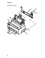
Страница 54: ...4076 0WJ 43 Assembly 1 Covers 2 6 5 3 1 4 7 8 9 ...
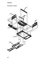
Страница 56: ...4076 0WJ 45 Assembly 2 Frames 2 3 4 1 6 5 7 ...
Страница 58: ...4076 0WJ 47 Assembly 3 Paper Feed 4 6 7 9 8 1 2 3 5 ...
Страница 60: ...4076 0WJ 49 Assembly 3 Paper Feed Cont 11 13 12 11 10 14 ...
Страница 62: ...4076 0WJ 51 Assembly 4 Electronics 4 5 4 3 2 1 8 6 7 9 10 11 ...
Страница 64: ...4076 0WJ 53 Assembly 4 Electronics Cont 4 5 4 3 2 1 8 6 7 9 10 11 ...
Страница 66: ...4076 0WJ 55 Assembly 4 Electronics Cont 13 10 11 9 12 ...
Страница 68: ...4076 0WJ 57 Assembly 5 Carrier 3 1 4 6 1 2 5 ...
Страница 70: ...4076 0WJ 59 Assembly 6 Carrier Transport 1 2 4 5 3 6 7 ...
Страница 72: ...4076 0WJ 61 Assembly 7 Auto Sheet Feed 6 13 5 2 10 3 9 14 1 11 10 12 4 8 7 ...
Страница 74: ...4076 0WJ 63 Assembly 8 Maintenance Station 3 1 4 2 ...


