4076-0WJ
27
Carrier Transport Motor Frame Removal
1. Remove the top cover.
2. Disconnect J6 from the system board.
3. Move the carrier in line with the opening in the carrier transport
motor frame.
4. Reach through the opening and pull the belt from the carrier.
5. Rotate the carrier guide rod top-to-rear to unlock the rod latches.
Gently push the carrier guide rod latches, at each end of the rod,
to the rear and lift up the rod until the sensor on the carrier clears
the encoder strip. Remove the carrier guide rod through the
opening in the left side frame. Be careful not to damage the
encoder strip.
A latch on the top front end of each side frame holds the transport
motor frame in place. Push up the latches on the front of the side
frames and pivot the carrier transport motor frame down and out of
the side frames.
Code Module Removal
1. Remove the top cover.
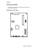
2. Disconnect the print head cables from the system board.
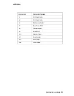
3. Disconnect connectors J4, J5, and J6 from the system board.
4. Remove the machine from the base. To do this, push the frame
latches out as you lift the machine from the base. Set the
machine aside.
5. Gently pry the code module from the system board.
Содержание WinWriter 100
Страница 54: ...4076 0WJ 43 Assembly 1 Covers 2 6 5 3 1 4 7 8 9 ...
Страница 56: ...4076 0WJ 45 Assembly 2 Frames 2 3 4 1 6 5 7 ...
Страница 58: ...4076 0WJ 47 Assembly 3 Paper Feed 4 6 7 9 8 1 2 3 5 ...
Страница 60: ...4076 0WJ 49 Assembly 3 Paper Feed Cont 11 13 12 11 10 14 ...
Страница 62: ...4076 0WJ 51 Assembly 4 Electronics 4 5 4 3 2 1 8 6 7 9 10 11 ...
Страница 64: ...4076 0WJ 53 Assembly 4 Electronics Cont 4 5 4 3 2 1 8 6 7 9 10 11 ...
Страница 66: ...4076 0WJ 55 Assembly 4 Electronics Cont 13 10 11 9 12 ...
Страница 68: ...4076 0WJ 57 Assembly 5 Carrier 3 1 4 6 1 2 5 ...
Страница 70: ...4076 0WJ 59 Assembly 6 Carrier Transport 1 2 4 5 3 6 7 ...
Страница 72: ...4076 0WJ 61 Assembly 7 Auto Sheet Feed 6 13 5 2 10 3 9 14 1 11 10 12 4 8 7 ...
Страница 74: ...4076 0WJ 63 Assembly 8 Maintenance Station 3 1 4 2 ...


