background image

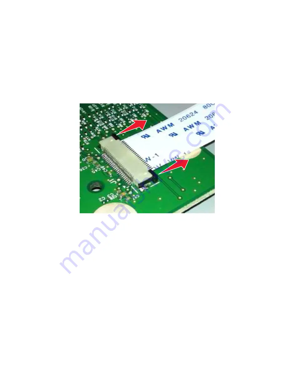
Horizontal sliding contact connector

This FRU contains a horizontal sliding contact connector. Read the instructions before proceeding.

The horizontal sliding contact connector uses a slide locking actuator to lock the ribbon cable into the Zero Insertion
Force (ZIF) connector. The cable is inserted horizontally into the connector.

Warning—Potential Damage: 

When opening or closing this type of actuator, gently push or pull the two tabs

located on each end of the actuator. Do not close the actuator from the center of the actuator. Do not use a
screwdriver to open or close the actuator. Damage to the cable or connector could occur.

Removing a cable from the horizontal sliding contact connector

1

Simultaneously slide the two tabs located on the ends of the locking actuator away from the connector.

2

Slide the cable out of the connector.

7016

Repair information

214

Содержание 7016-630

Страница 1: ...Lexmark MX610 MFP Machine Type 7016 630 670 675 Service Manual Start diagnostics Maintenance Safety and notices Trademarks Index October 19 2012 www lexmark com P N 12G2272 ...

Страница 2: ... or the programs described may be made at any time References in this publication to products programs or services do not imply that the manufacturer intends to make these available in all countries in which it operates Any reference to a product program or service is not intended to state or imply that only that product program or service may be used Any functionally equivalent product program or...

Страница 3: ...c information 35 Troubleshooting overview 35 Performing the initial troubleshooting check 35 Power on Reset POR sequence 36 Using Safe Mode 36 Fixing print quality issues 37 Initial print quality check 37 Gray background or toner fog on prints 38 Repeating defects 39 Printer is printing blank pages 39 Printer is printing solid black pages 40 Shadow images appear on prints 40 Skewed print 41 Streak...

Страница 4: ...isk must be formatted for use in this device 91 Disk near full Securely clearing disk space 91 Error reading USB drive Remove USB 92 Error reading USB hub Remove hub 92 Fax memory full 92 Fax partition inoperative Contact system administrator 92 Fax server To Format not set up Contact system administrator 92 Fax Station Name not set up Contact system administrator 92 Fax Station Number not set up ...

Страница 5: ...om standard output bin 98 Replace defective imaging unit 31 xy 98 Replace cartridge 0 estimated pages remain 88 xy 98 Replace imaging unit 0 estimated pages remain 84 xy 98 Replace maintenance kit 0 estimated pages remain 80 xy 98 Replace all originals if restarting job 99 Reinstall missing or unresponsive cartridge 31 xy 99 Reinstall missing or unresponsive imaging unit 31 xy 99 Replace unsupport...

Страница 6: ...service check 114 Cartridge gearbox service check 114 Tray 1 pick lift motor gearbox service check 115 171 xx Cooling fan service check 115 9xx error messages 116 System software error service check 119 NVRAM mismatch failure service check 123 Base printer symptoms 125 Dead machine service check 125 Controller board service check 126 Control panel service check 127 Toner starvation service check 1...

Страница 7: ...s 154 Escalating a fax issue to second level support 158 Service menus 161 Understanding the control panel and menus 161 Using the printer control panel 161 Understanding the colors of the indicator and Sleep button lights 161 Understanding the home screen 162 Using the touch screen buttons 164 Menus list 165 Diagnostics menu 166 Entering the Diagnostics menu 166 Registration 166 Scanner calibrati...

Страница 8: ...r manual registration 190 Disable scanner 191 Paper Prompts 192 Envelope Prompts 192 Action for Prompts 192 Jobs on Disk 193 Disk Encryption 193 Erase All Information on Disk 194 Wipe All Settings 194 Font Density 194 Font Sharpening 194 Reduced Curl 194 Require Standby 194 A5 Loading 195 UI Automation 195 LES Applications 195 Key Repeat Initial Delay 196 Key Repeat Rate 196 Clear Supply Usage His...

Страница 9: ...ce LIF connector 217 Printhead assembly adjustments 218 Removal procedures 221 Left side removals 221 Left cover removal 221 Main drive gearbox removal 223 MPF solenoid removal 225 MPF gearbox removal 227 Reverse solenoid removal 230 Cartridge gearbox removal 231 Duplex gear assembly removal 232 Right side removals 234 Right cover removal 234 Memory access door removal 237 Tray present sensor remo...

Страница 10: ...78 Bottom removals 281 Power supply removal 281 Power supply shield removal 281 Duplex removal 282 Duplex sensor and input sensor removal 283 Index sensor removal 286 Media present sensor removal 286 Toner density sensor removal 288 Trailing edge sensor removal 289 ACM assembly removal 290 Pick lift motor gearbox removal 296 Tray guide removal 296 Rear side removals 299 Dust cover removal 299 Rear...

Страница 11: ...inisher option removal 333 Stapler cartridge access door removal 334 Staple roll holder removal 335 Stapler right cover removal 336 Stapler left cover removal 336 Sensor stapler access door removal 338 Stapler carriage assembly removal 338 Stapler door close limit switch removal 340 Stapler rear cover removal 343 Sensor stapler rear cover removal 344 Trapped staple access door removal 346 Stapler ...

Страница 12: ...s 382 Parts catalog 384 Legend 384 Assembly 1 Covers 385 Assembly 2 Imaging 387 Assembly 3 Control panel 389 Assembly 4 Electronics 1 391 Assembly 5 Electronics 2 393 Assembly 6 Frame 395 Assembly 7 Option trays 397 Assembly 8 Staple finisher option 399 Assembly 9 Staple finisher right 401 Assembly 10 Staple finisher top 403 Assembly 11 Staple finisher rear 405 Assembly 12 Maintenance kits 407 Ass...

Страница 13: ...9 Paper path information 419 Input tray 419 Multipurpose feeder MPF 420 Simplex printing 420 Duplex printing 421 Media handling components 421 Main drive gearbox 421 Autocompensator mechanism ACM 422 Key components 422 Sensors 422 Other key components 423 Electrophotographic process EP process 424 ADF theory 428 ADF theory of operation 428 Appendix D Acronyms 431 Acronyms 431 Index 433 Part number...

Страница 14: ...7016 Table of contents 14 ...

Страница 15: ...etzt sind die die Werte für Klasse I überschreitet Avis relatif à l utilisation du laser L imprimanteestcertifiéeconformeauxexigencesdelaréglementationdesEtats Unis relativeauxproduits laser DHHS 21CFR Chapter I Subchapter J for Class I 1 Pour les autres pays elle est certifiée conforme aux exigences des normes IEC 60825 1 relatives aux produits laser de classe I Les produits laser de Classe I ne ...

Страница 16: ...s Laserinformatie Deze printer is in de Verenigde Staten gecertificeerd als een product dat voldoet aan de vereisten van DHHS 21 CFR hoofdstuk 1 paragraaf J voor laserproducten van klasse I 1 Elders is de printer gecertificeerd als een laserproduct van klasse I dat voldoet aan de vereisten van IEC 60825 1 Laserproducten van klasse I worden geacht geen gevaar op te leveren De printer bevat intern e...

Страница 17: ...aser og som opererer i bølgelengder på 655 675 nanometer Lasersystemet og skriveren er utformet slik at mennesker ikke utsettes for laserstråling utover nivået i klasse I under normal drift vedlikehold eller foreskrevet service Avís sobre el làser AlsEUA laimpressoraestàcertificadadeconformitatambelsrequisitsdelcapítolI apartatJdelCFR21delDepartament de Salut i Serveis Humans per a productes làser...

Страница 18: ... for this product has been prepared for use by a professional service person and is not intended to be used by others There maybean increased riskofelectricshockand personal injuryduring disassemblyandservicing ofthis product Professional service personnel should understand this and take necessary precautions CAUTION POTENTIAL INJURY The lithium battery in this product is not intended to be replac...

Страница 19: ...twortung oder Haftung für die Sicherheit übernommen Die Wartungsinformationen für dieses Produkt sind ausschließlich für die Verwendung durch einen Wartungsfachmann bestimmt Während des Auseinandernehmens und der Wartung des Geräts besteht ein zusätzliches Risiko eines elektrischen Schlags und körperlicher Verletzung Das zuständige Fachpersonal sollte entsprechende Vorsichtsmaßnahmen treffen VORSI...

Страница 20: ...utilitzen peces de recanvi no autoritzades La informació pel manteniment d aquest producte està orientada exclusivament a professionals i no està destinada a ningú que no ho sigui El risc de xoc elèctric i de danys personals pot augmentar durant el procés de desmuntatge i de servei d aquest producte El personal professional ha d estar ne assabentat i prendre les mesures convenients ATENCIÓ La bate...

Страница 21: ...当心一可能的伤害 本产品中的锂电池不可更换 如果不正确更换锂电池 可能会有爆炸危险 不要再 充电 拆解或 焚烧锂电池 丢弃旧的锂电池时应按照制造商的指导及当地法规进行处理 7016 Notices and safety information 21 ...

Страница 22: ...7016 22 ...

Страница 23: ...lustrations and part numbers for individual FRUs Appendix A contains detailed specifications about the product Appendix B contains the available options and other features of the product Appendix C contains the theory of operation Appendix D contains the list of acronyms in the manual and their meanings Service manual conventions Note A note provides additional information Warning Potential Damage...

Страница 24: ...7016 24 ...

Страница 25: ...lling parts See Parts catalog on page 384 to help identify parts Media guidelines Additional information for printing on specialty media may be found in the Cardstock and Label Guide available at http support lexmark com Paper guidelines Selecting the correct paper or specialty media reduces printing problems For the best print quality try a sample of the paper or specialty media before buying lar...

Страница 26: ...in direction Grain refers to the alignment of the paper fibers in a sheet of paper Grain is either grain long running the length of the paper or grain short running the width of the paper For 60 90 g m2 16 24 lb bond paper grain long paper is recommended Fiber content Most high quality xerographic paper is made from 100 chemically treated pulped wood This content provides the paperwith ahigh degre...

Страница 27: ... letterhead must be able to withstand temperatures up to 190 C 374 F without melting or releasing hazardous emissions Storing paper Use these paper storage guidelines to help avoid jams and uneven print quality For best results store paper where the temperature is 21 C 70 F and the relative humidity is 40 percent Most label manufacturers recommend printing in a temperature range of 18 24 C 65 75 F...

Страница 28: ...any of its variable characteristics such as moisture content thickness and texture can significantly impact print quality Print samples on the card stock being considered for use before buying large quantities From the Paper menu set the Paper Type to Card Stock Select the appropriate Paper Texture setting Be aware that preprinting perforation and creasing may significantly affect the print qualit...

Страница 29: ...2 kPa pressurewithout delaminating oozing around the edges or releasing hazardous fumes Do not use labels with slick backing material Use full label sheets Partial sheets may cause labels to peel off during printing resulting in a jam Partial sheets also contaminate the printer and the cartridge with adhesive and could void the printer and toner cartridge warranties Do not use labels with exposed ...

Страница 30: ...to prevent print quality problems Before loading transparencies flex fan and straighten the stack to prevent sheets from sticking together Supported paper sizes types and weights Supported paper sizes Paper size and dimension Standard 550 sheet tray Optional 250 or 550 sheet tray Multipurpose feeder ADF Scanner glass Duplex mode Business card X X X X X 3 x 5 in X X X X 4 x 6 in X X X X A4 210 x 29...

Страница 31: ...3 875 x 7 5 in X X X X X 9 Envelope 98 4 x 226 1 mm 3 875 x 8 9 in X X X X X 10 Envelope 104 8 x 241 3 mm 4 12 x 9 5 in X X X X X DL Envelope 110 x 220 mm 4 33 x 8 66 in X X X X X C5 Envelope 162 x 229 mm 6 38 x 9 01 in X X X X X B5 Envelope 176 x 250 mm 6 93 x 9 84 in X X X X X Other Envelope 85 7 x 165 mm to 215 9 x 355 6 mm 3 375 x 6 50 in to 8 5 x 14 in X X X X X Universal is supported in dupl...

Страница 32: ...lat when individually placed on a table facedown Data security notice This printer contains various types of memory that are capable of storing device and network settings information from embedded solutions and user data The types of memory along with the types of data stored by each are described below Volatile memory This device utilizes standard Random Access Memory RAM to temporarily buffer u...

Страница 33: ...he menu item under Configuration menu on page 186 pertaining to this To erase the printer hard disk see the menu item under Configuration menu on page 186 pertaining to this The following parts are capable of storing memory printer control panel UICC User Interface Controller Card controller board optional hard drives Note The printer control panel and controller board contain NVRAM After removing...

Страница 34: ...7016 34 ...

Страница 35: ...component allow the surface to cool before touching it Troubleshooting overview Performing the initial troubleshooting check on page 35 Power on Reset POR sequence on page 36 Using Safe Mode on page 36 Performing the initial troubleshooting check Before you start the troubleshooting procedures perform the following checks With the power cord unplugged from the wall outlet check that the cord is fr...

Страница 36: ...nly in the case of a non critical error when a print job must be completed before service can be arranged to repair the printer The printer must be returned to standard operating mode before diagnostics can be run or full function printing can continue You can enter Safe Mode in one of the following ways Enable Safe Mode from the Configuration menu and then POR the printer Press the Stop and Back ...

Страница 37: ...ponsibility of the customer With the customer s permission you might need to install a developer toner cartridge Initial print quality check Before troubleshooting specific print problems complete the following initial print quality check 1 The printer must be in a location that follows the recommended operating environment specifications See Operating environment on page 414 2 Check the life stat...

Страница 38: ...ridge plunger properly attached to the front door and is the spring functioning properly Go to step 2 Replace the cartridge plunger See Cartridge plunger removal on page 251 Step 2 Remove any contamination from the CTLS contacts Perform a print test Does the problem remain Go to step 3 The problem is solved Step 3 Check the CTLS for damage Is it free of damage Go to step 4 Replace the printer Step...

Страница 39: ...ser removal on page 302 Contact the next level of support Printer is printing blank pages Actions Yes No Step 1 Check the toner cartridge level Is the toner level low Replace the toner cartridge Go to step 2 Step 2 Check the imaging unit for wear or damage Is it free of wear or damage Go to step 3 Replace the imaging unit Step 3 Check the transfer roll for surface contamination or excessive wear I...

Страница 40: ... Actions Yes No Step 1 Check the imaging unit for damage Is it free of damage Go to step 2 Replace the imaging unit Step 2 Remove any contamination from the imaging unit contacts Does the problem remain Go to step 3 The problem is solved Step 3 Check the imaging unit contacts for damage Are they free of damage Replace the power supply See Power supply removal on page 281 Replace the printer Shadow...

Страница 41: ...removal on page 250 Step 4 Check the following fuser components for wear or damage Gears Exit rollers Belt fuser Are they free of damage Go to step 5 Replace the fuser See Fuser removal on page 302 Step 5 a Turn off the printer b Remove the rear door and cover c Disconnect the fuser cable connected to PCN5 of the power supply d Check for approximate correct resistance on the fuser cable 220V fuser...

Страница 42: ...ace the input tray Step 6 Make sure the MPF pick roller and separator pad are free of debris Check for wear or damage Are they free of wear or damage Go to step 7 Replace the MPF pick roller and separator pad See MPF pick roller removal on page 271 and Separator pad removal on page 278 Step 7 Check the MPF gearbox for wear or damage Is it free of wear or damage Go to step 8 Replace the MPF gearbox...

Страница 43: ... damage Contact the next level of support Replace the printer Streaked horizontal or vertical lines appear on prints ABCDE ABCDE ABCDE ABCDE ABCDE ABCDE Leading edge Trailing edge Actions Yes No Step 1 Check the imaging unit for wear or damage Is it free of wear or damage Go to step 2 Replace the imaging unit Step 2 Make sure the paper path is free of debris or toner contamination Does the problem...

Страница 44: ... 2 Tighten the screws Step 2 a Turn off the printer b Remove the rear door and cover c Disconnect the fuser cable connected to PCN5 of the power supply d Check for approximate correct resistance on the fuser cable 220V fuser 43 ohms 110V fuser 10 ohms 100V fuser 8 ohms Is the resistance equal to any of the above values Go to step 3 Replace the fuser See Fuser removal on page 302 Step 3 Check the f...

Страница 45: ...step 4 Replace the transfer roll Step 4 Remove the fuser and check for damage or debris on the rollers and belts Is it free of damage and debris Go to step 5 Replace the fuser Step 5 Reseat the cables JLSU1 and J6 on the controller board Does the problem remain Replace the LSU The problem is solved Paper jams Avoiding jams on page 46 Understanding jam messages and locations on page 47 200 paper ja...

Страница 46: ... it before printing or wait for a prompt to load it Do not load too much paper Make sure the stack height is below the maximum paper fill indicator Do not slide the paper into the tray Load paper as shown in the illustration Make sure the guides in the tray or the multipurpose feeder are properly positioned and are not pressing tightly against the paper or envelopes Push the tray firmly into the p...

Страница 47: ...rs on the printer display Open the doors covers and trays indicated on the display to remove the jam Notes When Jam Assist is set to On the printer automatically flushes blank pages or pages with partial prints to the standard bin after a jammed page has been cleared Check your printed output stack for discarded pages When Jam Recovery is set to On or Auto the printer reprints jammed pages However...

Страница 48: ... open rear door 20y xx Open the rear door and then remove the jammed paper 8 Finisher rear door x page jam remove all pages from the finisher s accumulator Leave paper in bin 45y xx Open the finisher rear door and then remove the jammed paper Open the trap door and then remove the jammed paper 9 Finisher output bin x page jam remove all pages from the output bin Leave paper in bin 45y xx Move the ...

Страница 49: ...printer might be hot To reduce the risk of injury from a hot component allow the surface to cool before touching it 1 Press the button on the right side of the printer and then open the front door 2 Pull out the toner cartridge using the handle 7016 Diagnostic information 49 ...

Страница 50: ...he imaging unit Doing so may affect the quality of future print jobs 4 Lift the green flap in front of the printer 5 Place the imaging unit aside on a flat smooth surface Warning Potential Damage Do not expose the imaging unit to direct light for more than 10 minutes Extended exposure to light may cause print quality problems 7016 Diagnostic information 50 ...

Страница 51: ...ligning the arrows on the side rails of the unit with the arrows on the side rails inside the printer and then insert the imaging unit into the printer 8 Insert the toner cartridge by aligning the side rails of the cartridge with the arrows on thesiderailsinside the printer and then insert the cartridge into the printer 7016 Diagnostic information 51 ...

Страница 52: ... 200 12 Printhead was not ready for media 200 13 Media at input sensor is not the next media to be imaged 200 14 Media reached the input sensor before EP was ready 200 15 Image data did not start on time 200 16 Fuser motor stalled Go to Main drive motor control jam service check on page 56 200 19 Page that was successfully picked from option tray never reached the input sensor Go to Sensor input e...

Страница 53: ...long over input sensor Sensor input static jam service check Action Yes No Step 1 Check the input sensor area for jammed media fragments Is the paper path free of partially fed or jammed media Go to step 2 Clear the paper path of any media fragments Step 2 Check the jam access cover if it is blocking the input sensor Is it blocking the input sensor Replace the jam access cover See Jam access cover...

Страница 54: ...ed test Does it move when doing the feed test Go to step 4 Replace the MPF solenoid See MPF solenoid removal on page 225 Step 4 Make sure the MPF gearbox spring is properly installed and free of damage Check the MPF gearbox for wear or damage Are they free of wear or damage Go to step 5 Replace the MPF gearbox See MPF gearbox removal on page 227 Step 5 Check the input sensor area for jammed media ...

Страница 55: ...ge 310 Step 3 Check the input sensor cable for proper connection Is it properly connected Go to step 4 Reseat the cable Step 4 POR into the Diagnostics menu and perform a feed test Diagnostics Menu Input Tray Tests Feed Tests Tray 1 Does it pass the test Go to step 5 Replace the LSU See Laser scanning unit LSU removal on page 310 Step 5 POR into the Diagnostics menu and perform a sensor test Diagn...

Страница 56: ...proper operation a Remove the main drive gearbox Note Do not disconnect the main drive gearbox cable b POR into the Diagnostics menu and perform a feed test Diagnostics menu Input Tray Tests Feed Test Select any input source c Check if the main drive motor rotates when doing the feed test Does it rotate when doing the feed test Go to step 4 Replace the main drive gearbox See Main drive gearbox rem...

Страница 57: ...ll down the rear door CAUTION HOT SURFACE The inside of the printer might be hot To reduce the risk of injury from a hot component allow the surface to cool before touching it 3 Firmly grasp the jammed paper on each side and then gently pull it out Note Make sure all paper fragments are removed 7016 Diagnostic information 57 ...

Страница 58: ...houtcover open Closeevent Likelythatthejam wasnotactually cleared 202 14 Expected banner sheet assumed wide not detected by narrow media sensor possible accordion jam unsupported narrow banner media or missing signal 202 16 Page at fuser nip before fuser started rampingtoward desired Indicates code may be receiving more hall interrupts than intended 202 17 Page at fuser nip before fuser reached ac...

Страница 59: ...gments Is the paper path free of partially fed or jammed media Go to step 2 Clear the paper path of any media fragments Step 2 Check the fuser exit sensor cable JEXIT1 for proper connection Is it properly connected Go to step 3 Reseat the cable Step 3 POR into the Diagnostics menu and perform a sensor test Diagnostics Menu Base Sensor Test Exit Does the sensor state on the control panel display ch...

Страница 60: ...plex 23y xx 1 Pull out the tray completely 2 Locate the lever and then pull it down to release the jam 3 Firmly grasp the jammed paper on each side and then gently pull it out Note Make sure all paper fragments are removed 7016 Diagnostic information 60 ...

Страница 61: ...plex sensor never made by leading edge of page 230 04 Page in duplexer ahead of current reversing page never staged 230 05 Internal duplex sensor never broke on the trailing edge of the sheet 230 07 Internal duplex sensor never broke from sheet ahead of page 230 09 Page in duplexer never picked 230 10 Narrow page reversing into duplexer 230 28 Bouncy duplex sensor never made 232 03 Input sensor ne...

Страница 62: ... wear and damage Go to step 4 Replace the duplex gear assembly See Duplex gear assembly removal on page 232 Step 4 From under the printer check the duplex belt and roller for wear and damage Are they free of wear and damage Go to step 5 Replace the duplex See Duplex removal on page 282 Step 5 a POR into the Diagnostics menu and navigate to DUPLEX TESTS Sensor Test b Lower the jam access cover and ...

Страница 63: ...scription Action 241 01 Paper over tray 1 pass thru sensor on warmup Go to Tray 1 jam service check on page 69 241 02 Sensor input early arriving jam 241 03 Tray 1 pass thru sensor never became covered when feeding a sheet from an option below 241 07 Option tray 1 pass thru sensor never became uncovered when feeding a sheet from an option below 241 13 The media is late reaching the sensor input wi...

Страница 64: ...in tray 1 Go to Tray 1 jam service check on page 69 241 29 Tray 1 lift plate failed to make the index sensor while elevating 241 32 Media tray not ready 241 33 The media tray was pulled during the media pick process 241 41 Media feeder motor stall in tray 1 Go to Tray 1 jam service check on page 69 241 42 Media feeder motor pick motor under speed in tray 1 241 43 Media feeder motor stalled on the ...

Страница 65: ...ither due to feed error or cartridge error Go to Option tray jam service check on page 70 242 15 Oneor more trays located above the source tray 2 has been pulled 242 16 The engine timed out waiting for the tray 2 to report ready before the 1st pick attempt 242 17 Page was not properly picked from tray 2 Have not exhausted all pick retry attempts as there are sheets committed to the paper path from...

Страница 66: ...er jam 243 01 Paper over tray 3 pass thru sensor on warmup 243 02 Input sensor detected late feed during a pick retry from tray 3 Go to Option tray jam service check on page 70 243 03 tray 3 pass thru sensor never became covered when feeding a sheet from an option below 243 06 Failed to feed from tray Paper present sensing supported and indicates media still in tray 243 07 Option tray 3 pass thru ...

Страница 67: ...rspeed Motor underspeed max PWM and motor underspeed typical accordion jam 243 43 Motor 1 Pick Lift motor ramp end ramp did not reach speed typical pack feed paper jam 243 44 Motor 2 Separator Passthru motor stalled 243 45 Motor 2 Separator Passthru motor PWM overflow error underspeed Motor underspeed max PWM and motor underspeed typical accordion jam Go to Option tray jam service check on page 70...

Страница 68: ...ray jam service check on page 70 244 17 Page was not properly picked from tray 4 Have not exhausted all pick retry attempts as there are sheets committed to the paper path from below 244 19 Tray 4 fail to feed error Detected while trying to pick a sheet and that leading edge was not detected by tray sensor 244 20 Took too long to ramp up dc feed motor in tray 4 244 21 Pick motor stall in tray 4 Go...

Страница 69: ...m service check Action Yes No Step 1 Restart the printer Does it fail to complete the POST sequence and display a 241 xx error Replace the index sensor Go to step 2 Step 2 Check the pick tires Are they free of wear or damage Go to step 3 Replace the pick tires Step 3 Check the separator roll assembly Is it free of wear or damage Go to step 4 Replace the separator roll assembly See Separator roll a...

Страница 70: ...x See MPF gearbox removal on page 227 Step 10 Check the main drive gearbox Is it free of wear or damage Go to step 11 Replace the main drive gearbox See Main drive gearbox removal on page 223 Step 11 Does the error remain Contact the next level of support The problem is solved Option tray jam service check Action Yes No Step 1 Restart the printer Does it fail to complete the POST sequence and disp...

Страница 71: ...Step 7 Check the ACM assembly Is it free of wear or damage Go to step 8 Replace the ACM assembly See ACM assembly removal on page 330 Step 8 POR into the Diagnostics menu and perform a feed test Diagnostics Menu Input Tray Tests Feed Test Select an option tray Does the pick lift motor gearbox pass the test Go to step 9 Replace the option tray Step 9 Does the error remain Contact the next level of ...

Страница 72: ...e the paper Straighten the edges on a level surface 3 Reload paper into the multipurpose feeder Note Make sure the paper guide lightly rests against the edge of the paper 4 From the printer control panel touch Done to clear the message and continue printing 7016 Diagnostic information 72 ...

Страница 73: ...ce check Action Yes No Step 1 Check the springs links and tray guides on the MPF assembly for damage Are they free of damage Go to step 2 Replace the MPF assembly See MPF tray removal on page 269 Step 2 a Make sure the MPF sensor cable is properly connected to the controller board b POR into the Diagnostics menu and perform a sensor test Diagnostics Menu Input Tray Tests Sensor Tests Multi Purpose...

Страница 74: ...PF gearbox removal on page 227 Step 6 Does the error remain Contact the next level of support The problem is solved 28y paper jams x page jam open automatic feeder top cover 28y xx 1 Remove all original documents from the ADF tray Note The message is cleared when the pages are removed from the ADF tray 2 Open the ADF cover 3 Firmly grasp the jammed paper on each side and then gently pull it out No...

Страница 75: ...Restart the MFP If the error recurs then see ADF paper jam service check on page 146 283 03 ADF Feed Jam LE of paper does not reach 1st Scan Sensor in time Remove the sheet of paper rom the ADF Retry the job If the error recurs then see ADF paper jam service check on page 146 283 05 1st Scan Sensor Jam TE never clears 1st Scan Sensor Remove the sheet of paper rom the ADF Retry the job If the error...

Страница 76: ...put bin Leave paper in bin 45y xx Paper jam in the finisher bin 1 Empty the standard bin 2 Move the tamper arms to the sides 3 Remove all jammed pages from inside the access areas Note Make sure all paper fragments are removed 7016 Diagnostic information 76 ...

Страница 77: ...to clear the message and continue printing Paper jam in the finisher rear door 1 Open the finisher rear door 2 Firmly grasp the jammed paper on each side and then gently pull it out Note Make sure all paper fragments are removed 7016 Diagnostic information 77 ...

Страница 78: ... any jammed paper in the finisher bin or in the finisher rear door open the trap door to remove any paper fragments 4 Close the trap door 5 Close the finisher rear door 6 If necessary touch Done from the printer control panel to clear the message and continue printing 7016 Diagnostic information 78 ...

Страница 79: ...le jam in the finisher 1 Open the staple access door 2 Pull out the staple cartridge from the finisher 1 2 3 Lift the staple guard and then remove any jammed or loose staples 7016 Diagnostic information 79 ...

Страница 80: ...nto place 5 Insert stapler cartridge back into the finisher until it clicks into place 6 Close the staple access door 7 If necessary touch Done from the printer control panel to clear the message and continue printing 7016 Diagnostic information 80 ...

Страница 81: ...finisher bin 1 Empty the standard bin 2 Move the tamper arms to the sides 3 Remove all jammed pages from inside the access areas Note Make sure all paper fragments are removed 4 If necessary touch Done from the printer control panel to clear the message and continue printing 7016 Diagnostic information 81 ...

Страница 82: ...e and then gently pull it out Note Make sure all paper fragments are removed 3 Open the finisher trap door and then remove any paper fragments from inside the trap door Note After removing any jammed paper in the finisher rear door open the trap door to remove any paper fragments 7016 Diagnostic information 82 ...

Страница 83: ...4 Close the trap door 5 Close the finisher rear door 6 If necessary touch Done from the printer control panel to clear the message and continue printing 7016 Diagnostic information 83 ...

Страница 84: ... main motor in the staple finisher 452 73 Staple finisher left tamper failed to leave its home position Go to Tamper motor jam service check on page 87 452 74 Staple finisher left tamper failed to reach its home position 453 75 Staple finisher right tamper failed to leave its home position 453 76 Staple finisher right tamper failed to reach its home position 454 41 Staple finisher ejector motor st...

Страница 85: ...ration 457 89 Staple failed to prime after a stapling operation 457 90 Staple failed to prime before a stapling operation Ejector jam service check Action Yes No Open the stapler service cover and check the ejector motor cable connection on the stapler controller board Is it properly connected If the error persists then replace the staple finisher option Go to Staple finisher option removal on pag...

Страница 86: ...sist Go to step 2 Go to step 5 Step 2 Open the stapler service cover and check all connectors on the stapler controller board Are all of them properly connected Go to step 3 Reseat all connections on the stapler controller board Step 3 Replace the stapler carriage assembly See Stapler carriage assembly removal on page 338 Does the error remain Go to step 4 The problem is solved Step 4 Replace the ...

Страница 87: ...he stapler controller board Are all of them properly connected Go to step 3 Reseat all connections on the stapler controller board Step 3 Replace the stapler carriage assembly See Stapler carriage assembly removal on page 338 Does the error remain Go to step 4 The problem is solved Step 4 Replace the stapler controller board See Stapler controller PCBA removal on page 347 Does the error remain Rep...

Страница 88: ...roblem is solved Step 5 Replace the stapler controller board See Stapler controller PCBA removal on page 347 Does the error remain Replace the staple finisher option Go to Staple finisher option removal on page 333 The problem is solved Understanding the printer messages Cartridge imaging unit mismatch 41 xy Install a toner cartridge that matches the region number of the printer x indicates the va...

Страница 89: ...g Load the correct size and type of paper in the tray then specify the paper size and type in the Paper menu on the printer control panel and then touch Finished changing paper Touch Reset active bin to reset the active tray for a linked set of trays Cancel the print job Change paper source to custom string load orientation Try one or more of the following Load the correct size and type of paper i...

Страница 90: ...k on If the error occurs again then 1 Turn off the printer 2 Unplug the power cord from the electrical outlet 3 Remove the tray 4 Contact customer support From the printer control panel touch Continue to clear the message and resume the job Close front door Close the front door of the printer Close flatbed cover and load originals if restarting job 2yy xx Try one or more of the following Touch Sca...

Страница 91: ...cted 51 Try one or more of the following Replace the defective flash memory card From the printer control panel touch Continue to ignore the message and continue printing Cancel the current print job Disk full 62 Try one or more of the following From the printer control panel touch Continue to clear the message and continue processing Delete fonts macros and other data stored in the printer hard d...

Страница 92: ...r control panel touch Continue to clear the message Complete the Fax Server setup If the message appears again then contact your system support person Fax Station Name not set up Contact system administrator Try either of the following From the printer control panel touch Continue to clear the message Complete the Analog Fax setup If the message appears again after completing the setup then contac...

Страница 93: ...anel Make sure the correct paper size and type are specified in Print Properties or the Print dialog settings Check if the paper size is correctly set For example if MP Feeder Size is set to Universal then make sure the paper is large enough for the data being printed Check the length and width guides and make sure the paper is loaded properly in the tray From the printer control panel touch Conti...

Страница 94: ... and type then it prints from the default paper source Cancel the current job Load paper source with custom string paper orientation Try one or more of the following Load the indicated tray or feeder with the correct size and type of paper To use the tray with the correct paper size or type touch Finished loading paper on the printer control panel Note If the printer finds a tray that has the corr...

Страница 95: ...e tray Cancel the print job Load Manual Feeder with custom string paper orientation Try one or more of the following Load the feeder with the correct size and type of paper From the printer control panel touch Prompt each page paper loaded or Do not prompt paper loaded to clear the message and continue printing From the printer control panel touch Automatically select paper to use the paper loaded...

Страница 96: ...ouch Continue to clear the message and continue printing Memory full 38 Try one or more of the following From the printer control panel touch Cancel job to clear the message Install additional printer memory Memory full cannot print faxes From the printer control panel touch Continue to clear the message without printing Held faxes attempt to print after the printer is restarted Memory full cannot...

Страница 97: ...arranty To accept any and all of these risks and to proceed with the use of non genuine supplies or parts in your printer press andhold and ontheprintercontrolpanelsimultaneouslyfor15secondstoclearthemessageandcontinueprinting If you do not wish to accept these risks then remove the third party supply or part from your printer and then install a genuine Lexmark supply or part Note For the list of ...

Страница 98: ... unit 31 xy Replace the defective imaging unit to clear the message For more information see the instruction sheet that came with the supply Note If you do not have a replacement imaging unit then see the Ordering supplies section of the User s Guide or visit www lexmark com Replace cartridge 0 estimated pages remain 88 xy Replace the toner cartridge For more information see the instruction sheet ...

Страница 99: ...y Try one or more of the following Check if the imaging unit is missing If missing install the imaging unit For information on installing the imaging unit see the Replacing supplies section of the User s Guide If the imaging unit is installed then remove the unresponsive imaging unit and then reinstall it Note If the message appears after reinstalling the supply then the imaging unit is defective ...

Страница 100: ... and automatically enable scanner to cancel the job Note This attempts to enable the scanner Scanner jam remove all originals from the scanner 2yy xx Remove the jammed paper from the scanner Scanner jam remove jammed originals from the scanner 2yy xx Remove the jammed paper from the scanner Serial port x disabled 56 Try one or more of the following From the printer control panel touch Continue to ...

Страница 101: ... to clear the message Enable the USB port From the printer control panel navigate to Network Ports USB Buffer Auto Note The printer discards any data received through the USB port Supply needed to complete job Do either of the following Install the missing supply to complete the job Cancel the current job Too many flash options installed 58 1 Turn off the printer 2 Unplug the power cord from the e...

Страница 102: ...electrical outlet 3 Remove the unsupported option card from the printer controller board and then replace it with a supported card 4 Connect the power cord to a properly grounded electrical outlet 5 Turn the printer back on USB port x disabled 56 From the printer control panel touch Continue to clear the message Notes The printer discards any data received through the USB port Make sure the USB Bu...

Страница 103: ...magingunitI2Cpackethasbeensentbutcodetimed out on receiving the data callback 31 63 Imaging unit security error in the send challenge sequence 31 64 Imaging unit ROM signature error 31 65 Imaging unit stuck busy status register and or CRI Arbiter register report busy 31 66 Toner failed to replenish into the imaging unit 32 10 Toner cartridge smart chip compatibility error 1 Check ifthetoner cartri...

Страница 104: ... not reoccur replace the wireless network option 2 If the problem remains replace the controller board 80 Maintenance kit Replace the maintenance kit and then reset the Maintenance counter 84 Imaging unit low 1 Replace the imaging unit 2 Make sure the imaging unit smart chip contact cable is properly connected to the controller board 3 Make sure the contacts are free of debris 4 Checkthecontactsfo...

Страница 105: ...eseat the cables Step 2 Check the imaging unit smart chip contact for damaged pins Is it free of damage Replace the controller board See Controller board removal on page 239 Replace the printer Printer cartridge mismatch service check Action Yes No Step 1 a Make sure the toner cartridge smart chip contact cable JARW1 is properly connected to the controller board b Make sure the toner cartridge sma...

Страница 106: ...Action Yes No Check if the firmware level is compatible with the hardware level Are they compatible Contact the next level of support Flash the correct firmware level Printer hardware errors 1xx error messages on page 108 111 xx LSU service check on page 111 Fuser service check on page 111 LVPS service check on page 112 Toner density sensor service check on page 112 CTLS service check on page 113 ...

Страница 107: ...service check on page 126 Control panel service check on page 127 Toner starvation service check on page 128 USB print service check on page 129 Front door not closed service check on page 130 Network service check on page 131 7016 Diagnostic information 107 ...

Страница 108: ...nverge 111 56 Closed loop printhead error amp Ki failed to converge 111 57 Closed loop printhead error while waiting for amp Ki to converge 111 58 Closed loop printhead error load scan regs state 111 59 Closed loop printhead error forward and reverse capture times differ by too much 111 60 Closed loop printhead sweep error check sweep accuracy state 111 61 Printhead drive control out of range due ...

Страница 109: ...y state control in time 121 26 Failed to reach temperature during warm up 121 28 Failed to reach EP warm up temperature in time 121 29 Fuser failed to reach pre heat temperature for motor start during warm up 121 30 Fuser failedtoreachprintingtemperaturebythetime a page reached the fuser 121 31 Fuser is too hot Global overtemp check 121 32 Open fuser main thermistor 121 33 Open fuser edge thermist...

Страница 110: ...133 08 Excessive CTLS noise 140 10 Transport motor halls not detected Go to Main drive gearbox service check on page 113 140 20 Transport motor took too long to stop 140 30 Transport motor unable to lock before motor ID 140 40 Transport motor overspeed detected 140 60 Transport motor unable to lock after motor ID 140 70 Transport motor out of lock detected 140 80 Transport motor excessive PWM or o...

Страница 111: ...JTHERM1 JEXIT and PCN5 free of damage Go to step 3 Replace the fuser See Fuser removal on page 302 Step 3 a Turn off the printer b Remove the rear door and cover c Disconnect the fuser cable connected to PCN5 of the power supply d Check for approximate correct resistance on the fuser cable 220V fuser 43 ohms 110V fuser 10 ohms 100V fuser 8 ohms Is the resistance equal to any of the above values Pe...

Страница 112: ...locking the toner density sensor Is it free of loose toner Go to step 2 Clean the sensor Step 2 Check the TDS for proper operation a Lower the ACM assembly b Move the toner density sensor wiper from left to right Does it move freely Go to step 3 Reinstall the wiper properly If it still cannot move freely replace the toner density sensor See Toner density sensor removal on page 288 Step 3 Check the...

Страница 113: ...k for any debris Is it free of debris Go to step 2 Remove the debris Step 2 Check the gears of main drive gearbox for wear or damage Are they free of wear or damage Go to step 3 Replace the main drive gearbox See Main drive gearbox removal on page 223 Step 3 Check the main drive motor for proper operation a Remove the main drive gearbox Note Do not disconnect the main drive gearbox cable b POR int...

Страница 114: ...ssembly removal on page 290 Cartridge gearbox service check Action Yes No Step 1 Check the gear on the toner cartridge for wear or damage Is it free of wear or damage Go to step 2 Replace the toner cartridge Step 2 Check the gears on the cartridge gearbox for proper rotation and for wear or damage Does it rotate properly and is it free of wear or damage Go to step 3 Replace the cartridge gearbox S...

Страница 115: ...earbox See Pick lift motor gearbox removal on page 296 Step 4 Replace the controller board Does this fix the problem The problem is solved Contact the next level of support 171 xx Cooling fan service check Action Yes No Step 1 a MakesurethatthecableJFAN1isproperlyconnectedtothecontroller board b Check if the cooling fan is rotating properly Is it rotating properly Go to step 2 Replace the cooling ...

Страница 116: ...oard EEPROM and control panel mirror xx codes 00 29 mismatch between system and mirror 30 60 mismatch between secure and system Warning Potential Damage When replacing any of the following components Control panel assembly Controller board assembly Replace only one component at a time Replace the required component and perform a POR before replacing a second component listed above If this procedur...

Страница 117: ...s replacethecontroller board Go to Controller board removal on page 239 959 02 Failure to authenticate Signature Verification Code 959 03 Signature Verification Code failed to authenticate a code partition 959 04 Jump to unverified address 959 05 Unknown Boot Failure 959 20 Pensive hardware failure Replace the controller board Go to Controller board removal on page 239 959 21 Pensive did not respo...

Страница 118: ...d in the emulation header or emulation file 1 Disable the Download Emulation 2 Program the download emulation into the firmware card again 3 If the above steps do not resolve the problem then replace the firmware card and download the emulation again 975 xx Network Error unrecognizable network port Call the next level of support 976 xx Network Error unrecoverable software error in network port 978...

Страница 119: ... if the problem is constant or intermittent Use the troubleshooting procedure below to isolate the issue Take any notes as instructed You will need that information in the event you need to contact your next level of support Note Before troubleshooting determine the operating system used when the error occurred If possible determine whether a PostScript or PCL file was sent to the device when the ...

Страница 120: ...nt the following Error log Menu settings page Network settings page Does the error remain while these pages were printing Go to step 31 Go to step 7 Step 7 Note Before performing this step write down the following information about the file being sent to the printer Application used Operating system Driver type File type PCL PostScript XPS etc a Reattach the communications cable b POR the printer ...

Страница 121: ...job Does the error remain Go to step 31 Go to step 13 Step 13 Is there optional memory installed Go to step 14 Go to step 16 Step 14 a Reinstall the memory b Send a print job to the printer Does the error remain Go to step 15 Go to step 16 Step 15 a Install a Lexmark recommended memory option b Send a print job to the printer Does the error remain Go to step 31 The problem is solved Step 16 Is the...

Страница 122: ... there an ISP option installed Go to step 22 The problem is solved Step 22 a Reinstall the first ISP option b POR the printer Does the error remain Go to step 24 Go to step 23 Step 23 Run a job to test the option Does the error remain Go to step 24 Go to step 26 Step 24 a Upgrade the firmware if it was not upgraded in a previous step Note Contact your next level of support for the correct firmware...

Страница 123: ...ep 26 Step 30 a Replace the faulty ISP option b POR the printer Does the error remain Go to step 31 Go to step 26 Step 31 Contact your next level of support You will need the following information Exact 900 xx error digits and complete error message Printed menu settings page Printed network settings page Device error log A sample print file if the error appears to be isolated to a single file Fil...

Страница 124: ...ced Go to step 3 Go to step 2 Step 2 Check the controller board assembly Was the controller board assembly recently replaced Go to step 4 Contact next level of support Step 3 Replace the current control panel assembly with the control panel assembly Go to Control panel assembly removal on page 256 Does the error remain Go to step 5 The problem is solved Step 4 Replace the current controller board ...

Страница 125: ...plugged in Go to step 3 Go to step 2 Step 2 Plug the machine in Did this fix the problem The problem is solved Go to step 3 Step 3 Check the power cord for continuity Is there continuity Go to step 4 Replace the power cord Step 4 Check the AC line voltage to the machine The voltage should be within the following limits for 110 machines 100 to 127 V ac for 220 V machines 200 to 240 V ac Is the volt...

Страница 126: ...POR the machine Did the control panel fuser fan and drive motor function at startup Go to step 2 Go to step 3 Step 2 Run some print jobs Did any errors occur There is no issue Go to step 3 Step 3 Check the cables on the controller board Are they connected properly Go to step 5 Go to step 4 Step 4 Properly connect all the cables on the controller board Did this fix the issue The problem is solved G...

Страница 127: ...nd controller board at the same time Each card contains the printer settings When either of these cards is new it obtains some of the settings from the other card Settings are lost when both are new and replaced at the same time Action Yes No Step 1 Check the conections on the UICC and controller board for proper connections Are they properly connected Go to step 3 Go to step 2 Step 2 Properly con...

Страница 128: ...tep 2 a Install a new cartridge plunger and spring See Cartridge plunger removal on page 251 b Print some pages Did this fix the problem The problem is solved Go to step 3 Step 3 Did a 201 22 error display Go to step 4 Go to step 5 Step 4 Try a different toner cartridge Did this fix the problem The problem is solved Go to step 5 Step 5 Check the connections between the cartridge gearbox and the co...

Страница 129: ...fy if the user s applications are setup correctly Are they setup correctly Go to step 4 Go to step 3 Step 3 Try a different application to run a print job Did the output print This is not a printer issue Go to step 4 Step 4 Check the print driver Is the correct driver being used and properly setup Go to step 6 Go to step 5 Step 5 Use a different driver Did this fix the issue The problem is solved ...

Страница 130: ... might keep the switch trigger from properly moving Is there dirt or debris Go to step 4 Go to step 5 Step 4 Remove the debris Did this resolve the issue The problem is solved Go to step 5 Step 5 Check pin 2 on J44 for 3 3 V and pin 3 for GND Are the voltages and grounds correct Go to step 6 Go to step 7 Step 6 Replace the interlock switch Did this resolve the issue The problem is solved Go to ste...

Страница 131: ...the network is wireless then go to step 3 Go to step 2 Step 2 Connect the Ethernet cable Does this fix the problem The problem is solved Go to step 3 Step 3 Check the printer s online status under Printers and Faxes on the host computer Delete all print jobs in the print queue Is the printer online and in a Ready state Go to step 5 Go to step 4 Step 4 Change the printer status to online Did this f...

Страница 132: ...e network drop for activity Is the network drop functioning properly Replace the controller board See Controller board removal on page 239 Contact the network administrator Step 15 Is the printer on the same wireless network as the other devices Go to step 17 Go to step 16 Step 16 Assign the correct wireless network to the printer Did this fix the problem The problem is solved Go to step 17 Step 1...

Страница 133: ...the next level of support Input output option hardware errors 3xx error messages Error code Description Action 321 51 Motor 1 Pick Lift motor no first encoder Go to Option tray pick lift motor service check on page 135 321 52 Motor 1 Pick Lift motor stop error 321 53 Motor 1 Pick Lift PWM underflow motor overspeed 322 54 Motor 2 Separator Passthru motor no first encoder Go to Option tray separator...

Страница 134: ...vice check on page 136 334 58 Motor 3 motor stop error 334 59 Motor 3 PWM underflow motor overspeed 335 60 Hardware error Board ID unknown Go to Option tray controller card service check on page 137 335 61 Hardware error Option type unknown 335 62 Hardware error Product ID unknown 335 63 Hardware error Sensors are not plugged on the board 341 51 Motor 1 Pick Lift motor no first encoder Go to Optio...

Страница 135: ...ple finisher interface main motor went over the normal speed Option tray pick lift motor service check Action Yes No Step 1 a Remove the option tray insert b Checktheliftplateandgearsforproperoperationbymovingthemetal plate Do the lift plate and gears move freely and are they free of wear or damage Go to step 2 Replace the tray insert Step 2 Check the pick lift motor for the following Gear tooth b...

Страница 136: ...the separator roll assembly See Separator roll assembly removal on page 328 Option tray ACM motor service check Action Yes No Step 1 Check the cable J11 on the option tray controller card Is it properly connected Go to step 2 Reseat the cable Step 2 a Remove the option tray insert and bypass the tray present sensor b POR into the Diagnostics Menu and perform a feed test Diagnostics Menu Feed Test ...

Страница 137: ...Staple finisher option removal on page 333 Reseat the ejector motor connector ADF Scanner hardware errors 8xx service error messages Error code Description Action 840 xx Scanner error 840 01 The scanner is disabled and can t be used Perform the Scanner disabled service check Goto Scannerdisablederrorservicecheck on page 138 840 02 This message is posted when the MFP PORs Enter the configuration me...

Страница 138: ...er From there select Enabled to change the settings to re enable the scanner module and then save the setting POR the MPF to operating mode Try running a copy from the ADF and flatbed Did the 840 xx error reoccur Go to step 2 The problem is solved Step 2 Re enter the Configuration mode and scroll to and select the Disable Scanner menu item Does the screen display ADF disabled or Auto Disabled Go t...

Страница 139: ...tings to re enable the scanner module and then save the setting POR the MPF to operating mode Try running a copy from the ADF and flatbed Did the 840 xx error reoccur Go to step 7 The problem is solved Step 7 Replace the ADF unit See ADF unit removal on page 316 PORthemachineinto Configuration menu Disable scanner From there select Enabled to change the settings to re enable the scanner module and...

Страница 140: ... connecting the ADF and flatbed to the controller board Are they properly connected Go to step 3 Go to step 2 Step 2 Re connect the cables to the controller board Did this fix the problem The problem is solved Go to step 3 Step 3 Enter diagnostics mode and navigate to SCANNER TESTS Sensor Test Perform the scanner sensor tests Navigate to SCANNER TESTS Motor Tests Perform the scanner motor tests Di...

Страница 141: ...k on page 146 Blank page See Black or blank page copy service check on page 142 Black page No dial tone See Modem fax card service check on page 150 Machine dials a number but fails to make a connection with another fax machine The other fax machine may be turned off Ask the fax recipient to check their machine Incoming fax has blank spaces or poor quality The sending fax machine may be faulty The...

Страница 142: ... solid black pages on page 40 Go to step 2 Step 2 Is the copy an ADF scan Go to step 4 Go to step 3 Step 3 Run a flatbed copy Is it blank or black Go to step 5 Go to step 4 Step 4 Did the sheet feed into the ADF Go to step 5 Perform an ADF paper feed test Step 5 IstheCCDribboncableproperlyconnectedtoJ30onthecontrollerboard Go to step 6 Properly connect the ribbon cable to JCIS1 Step 6 Replace the ...

Страница 143: ... Ensure that the flatbed motor cable JFB1 is connected Is the cable connected Go to step 2 Properly connect the cable Step 2 Replace the flatbed unit See Flatbed assembly removal on page 324 Is voltage present The problem is solved Go to step 3 Step 3 Replace the controller board See Controller board removal on page 239 Did this solve the problem The problem is solved Contact the next level of sup...

Страница 144: ...ould be GND Is voltage present and is it correct Replace the flatbed See Flatbed assembly removal on page 324 Replace the controller board See Controller board removal on page 239 Flatbed legal scan service check Action Yes No Step 1 Check the JPLEN1 connector on the controller board for proper connection Is it properly connected Go to step 3 Go to step 2 Step 2 Re connect the cable to the control...

Страница 145: ...Go to step 8 Step 4 On the bottom of the ADF cover inspect the ADF cover closed sensor actuator Does it move freely Go to step 6 Go to step 5 Step 5 Fix the actuator so it moves freely Does this fix the problem Issue resolved Go to step 6 Step 6 Remove the ADF rear cover and inspect the ADF cover closed sensor for dirt and debris Is there dirt and debris present Go to step 7 Go to step 8 Step 7 Cl...

Страница 146: ...k should be used if the paper feeds and jams in the ADF If the paper is not feeding into the ADF see ADF feed errors service check on page 148 Actions Yes No Step 1 If the ADF is multi feeding or shingle feeding then check for dirt on the ADF separator pad restraint pad and ADF separator rollers Are they dirty Clean them with a lint freeclothandisopropyl alcohol Replace the separator pad and restr...

Страница 147: ... 10 Is there dirt in the sensors or is the paper present actuator stuck Clean the sensors or removedebrisfromthe actuators Go to step 8 Step 11 Are the sensor actuators on the ADF mechanism cover damaged Replace the ADF Go to step 9 Step 12 Is the ADF connector properly connected to JADF1 on the system board Go to step 10 Properly connect the cable to the system board Step 13 Inspect the connectio...

Страница 148: ... ADF paper jam service check on page 146 Step 4 Is the leading edge of the paper wrinkled or torn Use different media Go to step 5 Step 5 Perform the ADF pick motor and ADF feed motor tests Are the motors working properly Go to step 6 Go to step 8 Step 6 Perform the ADF paper present sensor test See Scanner tests on page 181 Is the sensor working properly Go to step 7 Go to step 8 Step 7 Check the...

Страница 149: ...scanner sensor tests See Scanner tests on page 181 Are the sensors working properly Go to step 3 Go to step 4 Step 3 Check the ADF sensor actuators to see if they are dirty or jammed Are the actuators ok Go to step 4 Clean the actuators If any actuators on the ADF are broken then replace the ADF unit See ADF unit removal on page 316 Step 4 Check all of the connections on the ADF relay card Are the...

Страница 150: ...one line work properly Go to step 5 Go to step 4 Step 4 Use the MFP on a properly functioning phone jack Did this fix the problem Problem resolved Go to step 5 Step 5 Is the modem card ribbon cable properly connected to the system board at JMOD2 and the modem card Go to step 7 Go to step 6 Step 6 Properly connect the modem card cable to the modem card and system board Did this fix the problem Prob...

Страница 151: ...rly Go to step 5 Go to step 4 Step 4 Use the MFP on a properly functioning phone jack Did this fix the problem The problem is solved Go to step 5 Step 5 Is the phone line being used by the MFP an analog line Go to step 8 Go to step 6 Step 6 Is the line being used a VOIP line Go to step 7 Go to step 8 Step 7 Have the system administrator verify that the VOIP server is configured to receive faxes Is...

Страница 152: ...he Transmit Level setting in steps of 1db For example if default value is 11 db changing it to 12db will decrease the signal strength by 1db and changing it to 10db will increase the signal strength by 1db Recommended adjustment range is 5 db in 1db steps from the default value Did this fix the problem The problem is solved Gotoyoursecond level of support See Escalating a fax issue to second level...

Страница 153: ...Go to step 10 Step 10 Turn on Distinctive ring Did this fix the problem The problem is solved Go to step 11 Step 11 Is the phone line analog Go to step 13 Go to step 12 Step 12 IS the VOIP server configured to support fax Go to step 13 Stop here This is an issue with the VOIP provider Step 13 Does the MFP have reception issues with only a certain remote device Go to step 14 Go to step 15 Step 14 V...

Страница 154: ...n steps of 2db For example if default value is 43 db changing it to 45db will decrease the received signal level by 2db and changing it to 41db will increase the received signal level by 2db Recommended adjustment range is between 33db and 48db in 2db steps Did this fix the problem The problem is solved Go to step 20 Step 20 Press 411 to enter the SE Menu Select Print Logs Print the T30 transmissi...

Страница 155: ...tion scheme 802 Too many timeouts occurred during ECM reception If error persists then disable ECM mode 803 Fax cancelled by user No action needed 804 Unexpectedly received a disconnect command from the remote end Check line quality Adjust Transmit Level Receive Threshold values Remote device could be requesting an unsupported feature 805 Remote fax device failed to respond to the DCS command Adju...

Страница 156: ... to receive a good frame Adjust Receive Threshold 814 Tried too many times at selected speed using V34 modulation scheme Adjust Transmit Level Adjust to a lower modulation scheme 815 Fax transmission was interrupted due to power failure Troubleshoot MFP if error persists See Modem fax card service check on page 150 818 Fax transmission failed due to insufficient memory to store scanned image Adjus...

Страница 157: ...cessfully in V29 terminal modulation scheme Select a lower Max Speed under Fax Send settings Adjust the Transmit Level Check line quality 887 Failure to transmit training successfully in V27 terminal modulation scheme Select a lower Max Speed under Fax Send settings Adjust the Transmit Level Check line quality 888 Failure to transmit training successfully at 2400 bps in V27 terminal modulation sch...

Страница 158: ...ed A02 Received request for unsupported image resolution from remote fax device No action needed A03 Receivedrequestforunsupportedcompression type from remote fax device No action needed A04 Receivedrequestforunsupportedimagelength from remote fax device No action needed F00 Unknown error occurred No action needed Escalating a fax issue to second level support Beforecontactingthesecond levelsuppor...

Страница 159: ... the fields it can be retrieved from the SE menu The SE menu can be accessed by pressing 411 or typing http MFP IP address se in a Web browser 7 After all the requested information is entered into the Fax Checklist Web page press the Submit button on the bottom of the page A dialogue asking you to save the file will appear Note The file generated by the MFP is not automatically transmitted to seco...

Страница 160: ...7016 160 ...

Страница 161: ...puter Perform a power on reset POR with the main power switch Attach a device to the USB port on the printer 4 Keypad Enter numbers letters or symbols 5 Indicator light Check the status of the printer 6 Start button Start a job depending on which mode is selected 7 Cancel button Stop all printer activity 8 Clear All Reset button Reset the default settings of a function such as printing copying or ...

Страница 162: ...rinter is in Hibernate mode Understanding the home screen When the printer is turned on the display shows a basic screen referred to as the home screen Touch the home screen buttons and icons to initiate an action such as copying faxing or scanning to open the menu screen or to respond to messages Note Your home screen may vary depending on your home screen customization settings administrative se...

Страница 163: ...s Open a context sensitive Help dialog 14 Search held jobs Search for one or more of the following items User name for held or confidential print jobs Job names for held jobs excluding confidential print jobs Profile names Bookmark container or print job names USB container or print job names for supported file types Features Feature Description Menu trail line Example Menus Settings Copy Settings...

Страница 164: ...e the IP address when accessing the Embedded Web Server so you can view and remotely configure printer settings even when you are not physically near the printer Using the touch screen buttons Note Your home screen icons and buttons may vary depending on your home screen customization settings administrative setup and active embedded solutions 7 6 3 4 1 5 2 Touch To 1 Arrows View a list of options...

Страница 165: ...Loading Custom Types Custom Names1 Custom Scan Sizes Universal Setup Menu Settings Page Device Statistics Stapler Test Network Setup Page1 Network x Setup Page Shortcut List Fax Job Log Fax Call Log Copy Shortcuts E mail Shortcuts Fax Shortcuts FTP Shortcuts Profiles List Print Fonts Print Directory Print Demo Asset Report Active NIC Standard Network2 Standard USB Parallel x Serial x SMTP Setup Ed...

Страница 166: ...ings and operations used while manufacturing and servicing the printer Entering the Diagnostics menu 1 Turn off the printer 2 Press and hold 3 and 6 3 Turn on the printer 4 Release the buttons when the splash screen appears Registration These settings adjust the margins of the black plane To set the Registration 1 Print a Quick test page a From the Diagnostics menu navigate to Registration Quick T...

Страница 167: ...White Values are 10 to 10 The default value is 0 ADF Back White Values are 10 to 10 The default value is 0 Theseshouldonlybeusedtomanuallyadjustareplacementscanner Toadjustacalibrationvalue performthefollowing steps 1 Navigate to Diagnostics Scanner Calibration and touch Scanner Calibration 2 Select scanner calibration values 3 Select the value to be adjusted by touching it 4 Increment up from 0 t...

Страница 168: ... test pattern is printed on the first envelope the rest are blank The Print test page always prints single sided regardless of the duplex setting or the presence of the duplex option To run the Print Test 1 From the Diagnostics menu navigate to Print Tests 2 Select the paper source 3 Select any of the following Single Prints a single Print test page no buttons are active while the test page is pri...

Страница 169: ...plays PASSED and returns to the main section of the Hardware tests menu 3 Press X or Back to exit the test To run the test for the MS610de 1 From the Diagnostics menu navigate to Hardware Tests Button Test 2 With no buttons pressed a pattern matching the control panel buttons is displayed Press each control panel button one at a time and the panel highlights the represented button in the matching ...

Страница 170: ...ues may include Serial Wrap Serial 1 Wrap Serial 2 Wrap or Serial 3 Wrap Each time the test finishes the screen updates with the result P and F represent the same numbers for DRAM If the test passes the Pass Count increases by 1 However if the test fails one of the following failure messages appears for approximately three seconds and the Fail Count increases by 1 Receive Status Interrupt Error St...

Страница 171: ...plex top margin Use either Letter or A4 paper To run the Duplex quick test 1 From the Diagnostics menu navigate to Duplex Tests Quick Test 2 Choose any of the following Single Prints a single Quick test page Continuous Continuously prints the Quick test pages until X is pressed The printer attempts to print the Quick test page from the default paper source If the default paper source supports only...

Страница 172: ...value moves the text down the page and widens the top margin A negative value moves the text up the page and narrows the top margin 3 Depending on the printer model press OK or touch to save the desired margin value Left Margin This setting allows the user to shift the position of the left margin of the back side of a duplexed page to the left or right The default margin is 1 4 in To adjust this s...

Страница 173: ...rom the duplex unit and shut the duplex door 3 Press X to clear the message INPUT TRAY TESTS Feed Tests This test feeds blank pages through the paper path It can run using any of the paper or envelope sizes supported by the printer To run the Feed test 1 From the Diagnostics menu navigate to Input Tray Tests Feed Tests 2 Choose the input source All installed sources appear 3 Choose any of the foll...

Страница 174: ...3 Select one of the following Single Feeds a single page Continuous Continuously feeds pages until X is pressed Sensor Test This test verifies that the output bin sensors are working correctly To run this test 1 From the Diagnostics menu navigate to Output Bin Tests Sensor Test Standard Bin Testing appears while the printer is verifying the state of the sensor The control panel displays the curren...

Страница 175: ...s one block on each track saves the data and then writes and reads four test patterns to the bytes in the block If the block is good then the saved data is written back to the disk Note This test is available on the MS610de model only To run the quick disk test 1 From the Diagnostics menu navigate to Device Tests Quick Disk Test The power indicator blinks while the test is in progress Quick Disk T...

Страница 176: ...2 Do one of the following Depending on the printer model press OK or touch to continue Press X to cancel Note When the test starts it cannot be stopped or canceled 3 After the test is complete a message appears indicating a pass or fail result 4 Press X to return to the Device tests menu 5 Reformat the flash device using the Flash format setting in the Utilities menu PRINTER SETUP Defaults Warning...

Страница 177: ...ing will equal the values of the Picked Sides meter After all print tests have been completed the value will reset to zero Note The value of the setting cannot be changed manually Permanent Page Count The value of this setting indicates the total amount of pages that have been printed After all print tests have been completed the value will reset to zero Note The Permanent Page Count value cannot ...

Страница 178: ... curl on low grade paper and or melting of letterheads on some papers To adjust this setting 1 From the Diagnostics menu navigate to EP Setup Fuser Temp 2 Press OK or touch to save any changes Transfer Adjust This setting controls the transfer roll algorithm To adjust this setting 1 From the Diagnostics menu navigate to EP Setup Transfer Adjust 2 Press OK or touch to save any changes Print Contras...

Страница 179: ...ting executes the printer performs the following Calibrates its toner density sensor Measures the reflectivity of its bare drum Prints patches on the drum and measures the reflectivity of the drum through the patches Cleans the transfer roll Calculates reflectivity ratios and operating points to attain the darkness target of each operating point Modifies the EP mechanism as necessary to adjust ton...

Страница 180: ...eneral device information The specific events that appear in the report vary depending on the operational history of the printer Logs may be printed from the following events Job accounting log failures NV reset failures NV mirror entries 9xx and 1xx print engine service error entries Programming error entries Maintenance count reset entries Clear log entries Paper jam entries Firmware update entr...

Страница 181: ...ning If the scanner ASIC passed the test then the panel posts ASIC Test Passed Rebooting If the scanner ASIC failed the test then the panel posts ASIC Test Failed Rebooting Motor tests The motor tests allow you to test the functionality of the motors in the ADF unit ADF pick When Motor On is selected the device runs the pick motor continuously for five seconds and then automatically stops the moto...

Страница 182: ... Feed test This test enables a servicer to execute a continuous feed test from either the ADF or the flatbed The default is to perform the ADF test if paper is loaded into the ADF To perform the Feed Test do the following 1 Navigate to Diagnostic Menu Scanner Tests Feed Test 2 Press Select a paper size 3 Select your paper size A4 or Legal 4 Select the check button on the screen The screen displays...

Страница 183: ...test the Paper FB long test place a sheet of legal paper on the flatbed and close the cover If the sensor is working properly the indicator will change from 0 to 1 To test the Home sensor perform the following steps 1 Exit the sensor test 2 Open the flatbed cover 3 Use the carriage motor test to move the carriage out of the home position 4 Close the flatbed cover 5 Enter the sensor test If the hom...

Страница 184: ...D ADF cover open E Flatbed cover open F Paperfeed sensor 7016 Service menus 184 ...

Страница 185: ... and dark content 2 Perform a duplex copy If the back side of the resulting copy contains vertical streaks then the SE should clean the scanner glass and backing sheet execute the back side scan uniformity procedure and then perform another copy If streaks still appear on the resulting copy then the SE can repeat the cleaning and verification procedure a second time or can replace the ADF entirely...

Страница 186: ... exit Maintenance Counter Value When this is selected the printer displays the current value for the maintenance kit counter This counter tracks printer usage A print job containing a single page increments the counter by one while a duplex print job increments the counter by two When the value has reached the rated life of the maintenance kit it reminds the user that scheduled maintenance is requ...

Страница 187: ...ttings page from the Configuration menu 1 From the Configuration menu navigate to Reports Menu Settings Page 2 Depending on the printer model press OK or touch to print the page or press X to return to the Configuration menu Event Log This generates a printed report of the events detailed in the Print log See Print Log on page 180 To print the Event log from the Configuration menu 1 From the Confi...

Страница 188: ...e the setting 3 Select Submit 4 POR the printer Factory Defaults Warning Potential Damage This operation cannot be undone This setting enables a user to restore all of the printer settings to either the network settings on network models only or to the base printer settings To restore Factory Default settings 1 From the Configuration Menu navigate to Factory Defaults 2 Select from the available op...

Страница 189: ...rmit or sleep auto 3 Select to accept the setting or press the X on the screen to exit the item Min copy memory Values will be displayed only if the amount of installed DRAM is at least twice the amount of the value that is at least 200 MB of installed DRAM is required to display the 100 MB selection To change this setting 1 Select Min Copy Memory from the Configuration Menu setting s current valu...

Страница 190: ...ack to cancel and return to the Configuration Menu Flatbed edge erase This menu item sets the size in millimeters of the no print area around a flatbed scan job Copy jobs will use the setting or two millimeters whichever is larger To adjust the flatbed edge erase setting perform the following steps 1 Select FB Edge Erase from the Configuration Menu setting s current value displays 2 Select minus t...

Страница 191: ...y register the flatbed perform the following steps 1 In the Configuration Menu select the Scanner Manual Registration menu item 2 Select the Print Quick Test Page menu item 3 To view and adjust the flatbed registration place the quick test page into the flatbed 4 Select the Copy Quick Test Page item 5 After the quick test page copies select Flatbed 6 Use the plus or minus to increase or decrease t...

Страница 192: ...2 may override the value of this setting To change this setting 1 From the Configuration menu navigate to Envelope Prompts 2 Select from the available options Auto default Multi purpose Feeder Manual Envelope 3 Depending on the printer model press OK or touch to save the setting or press X to return to the Configuration menu without saving any changes When it is set to Auto the emulator selected t...

Страница 193: ... affect Print and Hold or parked jobs To change the setting 1 From the Configuration menu navigate to Jobs on Disk 2 Select from the available options to change the setting Delete Do Not Delete default 3 Press X to return to the Configuration menu Disk Encryption Warning Potential Damage If the settings are changed then the printer completely formats the hard disk All information on the disk will ...

Страница 194: ...hile a disk wipe operation is executing then Corrupt Disk appears upon regaining power Wipe All Settings This makes any sensitive information that may exist on the volatile or non volatile storage of the device completely indecipherable When selected the printer performs a non critical NVRAM reset and then reboots Font Density This creates microscopic holes in all black text The holes save toner b...

Страница 195: ...paper in the short edge feed orientation from all trays UI Automation Once enabled this setting creates an ENABLE_UI_AUTOMATION file in the var fs shared directory As long as this file exists the printer permits external developers to test the stability of their applications against the printer to make sure that their applications have an appropriate level of stability Disabling this setting delet...

Страница 196: ... 30 with increments of 1 To adjust this setting 1 From the Configuration Menu navigate to Key Repeat Rate 2 Touch the arrow keys to adjust the setting 3 Touch to save the setting or press X to return to the Configuration Menu without saving any changes Clear Supply Usage History This setting reverts the supply usage history number of pages and days remaining to the factory shipped level To clear t...

Страница 197: ... the printer remains inactive for a length of time equal to the Screen timeout setting To change this setting 1 From the Configuration menu navigate to Automatically Display Error Screens 2 Select from the available options On default Off 3 Depending on the printer model press OK or touch to save the setting or press X to return to the Configuration menu without saving any changes USB PnP In some ...

Страница 198: ...td Network Setup 2 Press and hold 6 7 and 9 simultaneously Service Engineer menu Accessing the service engineer SE menu From a Web browser on a host PC add se to the printer IP address Service engineer SE menu This menu should be used as directed by the next level of support Top level menu Intermediate menu Print SE Menus General Copyright Displays copyright information Code Revision Info Network ...

Страница 199: ...tech Mode RAW LPR Mode Gather Debug Enable Debug Fax service engineer SE menu The Fax SE menu is used for the Fax transmission service check and the Fax reception service check It should only be used as directed by the next level of support In Ready mode type 411 to enter the Fax SE menu 7016 Service menus 199 ...

Страница 200: ...7016 200 ...

Страница 201: ...M to temporarily buffer user data during simple print and copy jobs Non volatile memory This device may utilize two forms of non volatile memory EEPROM and NAND flash memory Both types are used to store the operating system device settings network information scanner and bookmark settings and embedded solutions Hard disk memory Some devices have a hard disk drive installed The printer hard disk is...

Страница 202: ...r body through the ESD sensitive part Large metal objects can be discharge paths without being grounded Prevent ESD sensitive parts from being accidentally touched by other personnel Install machine covers when you are not working on the machine and do not put unprotected ESD sensitive parts on a table If possible keep all ESD sensitive parts in a grounded metal cabinet case Be extra careful while...

Страница 203: ... needs to replace the RIP board the steps below should be taken to backup the eSF solutions and settings 1 POR the printer into invalid engine code mode 2 Open a Web browser and navigate to the printer Web page 3 Navigate to Settings and click the link 4 Navigate to Solutions and click the link 5 Navigate to Embedded Solutions and click the link 6 On the Embedded Solutions page select the apps to ...

Страница 204: ...e contacts always face away from the actuator Warning Potential Damage Do not insert the cable diagonally into the ZIF socket This can cause damage to the contacts on the cable Warning Potential Damage Avoid using a fingernail or sharp object to open the locking mechanism This could damage the cable Warning Potential Damage Avoid pressing against the cable when opening the locking mechanism This c...

Страница 205: ...ally into the connector Warning Potential Damage When opening or closing this type of actuator gently lift or close the two tabs located on each end of the actuator The two tabs should be moved simultaneously Do not close the actuator from the center of the actuator Removing a cable from the horizontal top contact connector 1 Place a finger at each end of the locking actuator and then gently lift ...

Страница 206: ...n The tabs on the ends of the actuator are vertical when the actuator is unlocked 2 Insert the cable with the contacts on the cable facing up Insert the cable on top of the actuator Note Verify that the cable is installed squarely into the connector If the cable is not squarely installed then intermittent failures could occur 7016 Repair information 206 ...

Страница 207: ... actuator to the locked position The cable should not move while this step is performed If the cable moves open the actuator reposition the cable and then close the actuator to the down position 7016 Repair information 207 ...

Страница 208: ...connector Warning Potential Damage When opening or closing this type of actuator gently lift the center of the actuator using your finger Do not use a fingernail or screwdriver to open the actuator This could damage the ribbon cable Do not close the actuator from the ends of the actuator Removing a cable from the horizontal bottom contact connector 1 Placetwofingerstowards eachendofthelockingactua...

Страница 209: ...rt the cable into the ZIF connector with the contacts facing downward and away from the locking actuator The cable needs to be inserted below the actuator Note Verify that the cable is installed squarely into the connector If the cable is not squarely installed then intermittent failures could occur 7016 Repair information 209 ...

Страница 210: ...3 Place your finger in the middle of the actuator and then rotate the locking actuator to the locked position 7016 Repair information 210 ...

Страница 211: ... connector Warning Potential Damage When opening or closing this type of actuator gently lift the center of the actuator using your finger Do not use a fingernail or screwdriver to open the actuator This could damage the ribbon cable Do not close the actuator from the ends of the actuator Removing a cable from the vertical mount contact connector 1 Gently rotate the locking actuator from the cente...

Страница 212: ...or to verify it is in the open position 2 Insertthecablewiththecontactsonthecableawayfromthelockingactuator Insertthecableontopoftheactuator Note Verify that the cable is installed squarely into the connector If the cable is not squarely installed then intermittent failures could occur 7016 Repair information 212 ...

Страница 213: ... position by pressing down on both ends of the actuator The cable should not move when this step is performed If the cable moves open the actuator reposition the cable and then close the actuator to the down position 7016 Repair information 213 ...

Страница 214: ...arning Potential Damage When opening or closing this type of actuator gently push or pull the two tabs located on each end of the actuator Do not close the actuator from the center of the actuator Do not use a screwdriver to open or close the actuator Damage to the cable or connector could occur Removing a cable from the horizontal sliding contact connector 1 Simultaneously slide the two tabs loca...

Страница 215: ...actuator to verify it is in the open position If you are opening the connector pull back on both end tabs using equal force to avoid breaking the connector 2 Insert the cable with the contacts on the cable facing away from the locking actuator Insert the cable on top of the actuator 7016 Repair information 215 ...

Страница 216: ...rds the connector locking the cable into place The cable should not move when this step is performed If the cable moves open the actuator reposition the cable and then close the actuator to the down position 7016 Repair information 216 ...

Страница 217: ...ooking at the connector take note on which side the contacts are located Many boards will have the word contacts stamped on them to indicate which side of the LIF has the contacts When looking at the board take note that the contacts from the board to the connector are located on the side of the connector with the contacts 2 Insert the cable squarely into the connector Note Verify that the cable i...

Страница 218: ...ntal lines to appear skewed while the vertical lines remain parallel to the vertical edges There are no adjustments for skew Check the pick tires for wear the paper path for obstructions the fuser for proper setting and the tray paper guides for fit to the media Paper feed skew Printhead misalignment To adjust the printhead 1 POR into the Diagnostics menu and print a Quick test page Diagnostics Me...

Страница 219: ...nthead counterclockwise 5 Print another Quick test page and check if adjustments are still needed 6 After obtaining a properly adjusted image on the paper tighten all the screws 7 Align the printhead electronically Printhead assembly electronic adjustment Note Before aligning the printhead electronically first align the printhead mechanically 1 POR into the Diagnostics menu and print a Quick test ...

Страница 220: ...nt Right margin setting is 2 and the darkest bar is at 3 then the right margin setting will be equal to 1 2 3 1 4 Choose and save the desired Right margin setting 5 Print another Quick test page and check if the darkest bar is at zero If it is then check to see if the left top and bottom margins are detected If the darkest bar is not at zero then repeat steps 3 and 4 Note The alignment of the left...

Страница 221: ...ging unit should be carefully set on a clean smooth and flat surface It should also be protected from light while out of the device Disconnect all external cables from the printer to prevent possible damage during service Unless otherwise stated reinstall the parts in reverse order of removal When reinstalling a part held with several screws start all screws before the final tightening Left side r...

Страница 222: ...3 Release the two tabs B on the bottom of the cover 4 Pull the cover forward and remove it from the printer 7016 Repair information 222 ...

Страница 223: ...Main drive gearbox removal 1 Remove the left cover See Left cover removal on page 221 2 Squeeze the latch and then detach the link from the front door 7016 Repair information 223 ...

Страница 224: ...3 Remove the 4 screws A and then remove the main drive gearbox 4 Disconnect the cable from the main drive gearbox 7016 Repair information 224 ...

Страница 225: ...and the fuser gear C MPF solenoid removal 1 Remove the left cover See Left cover removal on page 221 2 Remove the main drive gearbox See Main drive gearbox removal on page 223 3 Remove the screw A 7016 Repair information 225 ...

Страница 226: ...ated displacement connector IDC Note Make sure the stripped end of the wire is positioned under the contact element d Insert a wire of the same color from the solenoid into the other end of the IDC Note Make sure the stripped end of the wire is positioned under the contact element e Squeeze the IDC to partially lock the wires in place and then use a pair of pliers to crimp the IDC f Repeat steps c...

Страница 227: ... left cover See Left cover removal on page 221 2 Remove the main drive gearbox See Main drive gearbox removal on page 223 3 Remove the front access cover See Front access cover removal on page 274 4 Disconnect the spring from the printer A 7016 Repair information 227 ...

Страница 228: ...5 Remove the three screws B and then remove the front left mount 6 Remove the three screws C and then remove the MPF gearbox 7016 Repair information 228 ...

Страница 229: ...7 Release the two latches D and then remove the main input drive gears 7016 Repair information 229 ...

Страница 230: ...val on page 221 3 Remove the rear door and cover See Rear exit door removal on page 299 and Rear cover removal on page 300 4 Remove the scanner assembly See Scanner assembly removal on page 318 5 Remove the top cover See Top cover removal on page 306 6 Remove the cooling fan See Cooling fan removal on page 238 7 Disconnect cable JDSOL1 from the controller board 7016 Repair information 230 ...

Страница 231: ...e reverse solenoid Cartridge gearbox removal 1 Remove the left cover See Left cover removal on page 221 2 Remove the four screws A securing the cartridge gearbox 3 Disconnect the cable from the cartridge gearbox 7016 Repair information 231 ...

Страница 232: ...val on page 300 3 Remove the power supply See Power supply removal on page 281 4 Remove the power supply shield See Power supply shield removal on page 281 5 Remove the duplex See Duplex removal on page 282 6 Position the printer so that it sits on its right side 7 Remove the E clip A 8 Remove the screw B 9 Remove the screw C 10 Remove the three gears 7016 Repair information 232 ...

Страница 233: ...11 From behind the three gears remove the duplex coupling D 12 Remove the duplex link E from the duplex 7016 Repair information 233 ...

Страница 234: ...ght side removals Right cover removal 1 Remove the paper tray 2 Remove the screw A securing the the right cover to the front of the printer frame 3 Open the memory access cover 7016 Repair information 234 ...

Страница 235: ...4 Remove the two screws B securing the right cover to the RIP shield 5 Open the front cover 7016 Repair information 235 ...

Страница 236: ...6 Slightly lift the printer slide the right cover forward and pull out and away from the printer 7016 Repair information 236 ...

Страница 237: ...uring the access door to the right cover 3 Slide the access door to release the hinges then remove it from the right cover Tray present sensor removal 1 Remove the right cover See Right cover removal on page 234 2 Disconnect the cable from the tray present sensor A 7016 Repair information 237 ...

Страница 238: ...4 Release the three latches C and then remove the tray present sensor Cooling fan removal 1 Remove the right cover See Right cover removal on page 234 2 Disconnect the cable JFAN1 from the controller board 7016 Repair information 238 ...

Страница 239: ... See Right cover removal on page 234 2 Remove the controller board shield See Controller board shield removal on page 241 3 Disconnect all internal options attached to the board memory card internal solutions port hard disk 4 Disconnect all cables from the controller board 7016 Repair information 239 ...

Страница 240: ...5 Remove the screw A from the rear side of the printer 7016 Repair information 240 ...

Страница 241: ...led perform scanner manual registration see Scanner manual registration on page 190 and printhead registration see Printhead assembly adjustments on page 218 Controller board shield removal 1 Remove the right cover See Right cover removal on page 234 2 Remove the optional hard disk if present 7016 Repair information 241 ...

Страница 242: ...3 Loosen the two screws A securing the shield to the front of the printer frame 7016 Repair information 242 ...

Страница 243: ...4 Remove the screw B on the top left side of the shield 5 Remove the screw C on the top right side of the shield 7016 Repair information 243 ...

Страница 244: ...ip contact removal 1 Remove the right cover See Right cover removal on page 234 2 Remove the controller board shield See Controller board shield removal on page 241 3 Remove the controller board See Controller board removal on page 239 4 Remove the two screws A 7016 Repair information 244 ...

Страница 245: ... the right cartridge guide 6 From behind the right cartridge guide release the 4 latches C to detach the toner cartridge smart chip contact Note Pay attention to the original position of the spring and the actuators 7016 Repair information 245 ...

Страница 246: ... c Release the cartridge actuator The cartridge lock should move back to its original position Modem removal 1 Remove the right cover See Right cover removal on page 234 2 Remove the controller board shield See Controller board shield removal on page 241 3 Disconnect the modem connector JFAX1 from the controller board 7016 Repair information 246 ...

Страница 247: ...er board shield 5 Lift the modem to release and then remove Front removals Left front mount removal 1 Remove the left cover See Left cover removal on page 221 2 Remove the front access cover See Front access cover removal on page 274 7016 Repair information 247 ...

Страница 248: ...left front mount Right front mount removal 1 Remove the right cover See Right cover removal on page 234 2 Disconnect all control panel cables from the controller board 3 Disconnect the cable JCVR1 from the controller board 7016 Repair information 248 ...

Страница 249: ...4 Remove the four screws B and then remove the right front mount 7016 Repair information 249 ...

Страница 250: ...roll with bare hands Oil from the skin can damage it 1 Squeeze the latches at each end of the transfer roll 2 Lift to remove the transfer roll Warning Potential Damage Do not remove the spring under the left latch Doing so will damage the printer 7016 Repair information 250 ...

Страница 251: ...Cartridge plunger removal 1 Open the front door 2 Tilt the cartridge plunger 7016 Repair information 251 ...

Страница 252: ...3 Twist and then remove the cartridge plunger Installation notes a Use a spring hook to hold the spring and then reinstall the cartridge plunger 7016 Repair information 252 ...

Страница 253: ...b Set the spring over the plunger Name plate cover removal 1 Open the front door 2 Remove the two screws A securing the right side of the name plate cover 7016 Repair information 253 ...

Страница 254: ...3 Remove the two screws B securing the left side of the name plate cover 4 Release the tabs on top of the cover and then remove the name plate cover 7016 Repair information 254 ...

Страница 255: ... name plate cover See Name plate cover removal on page 253 2 Remove the two screws A securing the front bin cover to the front access cover 3 Lift the left side of the cover and then remove the front bin cover 7016 Repair information 255 ...

Страница 256: ...Control panel assembly removal 1 Open the wireless card cover 2 Lift the display to access the latch 3 Press the latch A to release the display from the panel mount 7016 Repair information 256 ...

Страница 257: ...4 Position the display at the angle shown to access the screws behind it 5 Remove the two screws B behind the display 7016 Repair information 257 ...

Страница 258: ...curing the control panel assembly to the scanner assembly 7 Gently flex the wireless chamber wall to the left to release and lift the control panel assembly upward to remove it from the scanner assembly 7016 Repair information 258 ...

Страница 259: ...roid bracket to the control panel cover 9 Unlock the connector E on the UICC and disconnect it from the UICC Warning Potential Damage The ZIF connector is prone to damage Extra care is required in handling this part 7016 Repair information 259 ...

Страница 260: ...panel assembly removal on page 256 2 Position the display at the angle shown to access the card behind it 3 Disconnect the UICC video cable A from the interface card 4 Place the operator panel assembly facedown on a non marring surface 7016 Repair information 260 ...

Страница 261: ...5 Remove the four screws B then remove the UICC drip pan from the control panel assembly 6 Disconnect the UICC video cable from the UICC card 7016 Repair information 261 ...

Страница 262: ... 1 Remove the two screws A 2 Remove the USB cable bracket Speaker removal 1 Remove the control panel assembly See Control panel assembly removal on page 256 2 Unplug the connector A from the speaker 7016 Repair information 262 ...

Страница 263: ...emove the control panel assembly See Control panel assembly removal on page 256 2 Push the latches inward and push down on the cave light lens to remove it from the scanner assembly Installation warning Gently push the left and right latches together while inserting the lens into the slot to avoid breaking the latches 7016 Repair information 263 ...

Страница 264: ...e wireless cover 2 Position the display at the angle shown to access the card behind it 3 Unlock the two connectors A on the interface card to release and then disconnect the UICC video and display cables A 7016 Repair information 264 ...

Страница 265: ...4 Remove the screw B then remove the interface card Control panel cover removal 1 Flex the frame to the right to release the hinge of the cover 7016 Repair information 265 ...

Страница 266: ...ontrol panel cover Display removal 1 Remove the control panel assembly See Control panel assembly removal on page 256 2 Position the display at the angle shown to access the card behind it 7016 Repair information 266 ...

Страница 267: ...rom the interface card 4 Release the two tabs B fastening the display bezel then separate both the display and bezel from the display assembly 5 Place the display and bezel facedown on a scratch free surface 7016 Repair information 267 ...

Страница 268: ...embly removal 1 Remove the control panel assembly See Control panel assembly removal on page 256 2 Remove the UICC See UICC removal on page 260 3 Remove the display See Display removal on page 266 4 Remove the interface PCBA See Interface card removal on page 264 The keypad assembly remains 7016 Repair information 268 ...

Страница 269: ...front access cover See Front access cover removal on page 274 2 Using a spring hook remove the two springs from the front access cover 3 Disconnect the left and right MPF links from the front access cover 7016 Repair information 269 ...

Страница 270: ...ccess cover 5 Slide the tray to the right and remove the MPF tray and spring Installation note Insert the straight end of the spring into the hole on the front access cover before sliding the MPF tray onto the left pivot of the front access cover 7016 Repair information 270 ...

Страница 271: ...emove the two screws A and then remove the MPF pick roller cover MPF pick roller removal 1 Remove the MPF pick roller cover See MPF pick roller cover removal on page 271 2 Remove the two screws A Note Use a 1 Phillips screwdriver 7016 Repair information 271 ...

Страница 272: ...e Warning Potential Damage Do not touch the pick tire with bare hands as this can damage the pick roller Bail removal 1 Remove the MPF pick roller cover See MPF pick roller cover removal on page 271 2 Rotate the bail 7016 Repair information 272 ...

Страница 273: ...s cover removal 1 Remove the MPF pick roller cover See MPF pick roller cover removal on page 271 2 Remove the MPF pick roller See MPF pick roller removal on page 271 3 Remove the four screws A and then remove the jam access cover 7016 Repair information 273 ...

Страница 274: ...Front access cover removal 1 Remove the name plate cover See Name plate cover removal on page 253 2 Disconnect the cartridge gear linkage A from the front access cover 7016 Repair information 274 ...

Страница 275: ...aligns the gap on the cover with the right hinge 4 Release the right hinge off the pivot by lifting up on the right side of the front access cover 5 Slide the front access cover to the right removing it from the print engine 7016 Repair information 275 ...

Страница 276: ...Remove the right cover See Right cover removal on page 234 2 Remove the MPF pick roller cover See MPF pick roller cover removal on page 271 3 Remove the MPF pick roller See MPF pick roller removal on page 271 4 Remove the jam access cover See Jam access cover removal on page 273 5 Remove the MPF tray See MPF tray removal on page 269 6 Disconnect cable JMPF1 from the controller board 7016 Repair in...

Страница 277: ...straint to release the MPF shaft 9 Rotate the MPF shaft inward so that the cams at each end point up 10 Release the front guide from the guides at each end Installation note The cams at each end of the MPF shaft must point down 7016 Repair information 277 ...

Страница 278: ...r See Front access cover removal on page 274 3 Remove the MPF pick roller cover See MPF pick roller cover removal on page 271 4 Remove the MPF pick roller See MPF pick roller removal on page 271 5 Remove the jam access cover See Jam access cover removal on page 273 6 Remove the E clip A 7016 Repair information 278 ...

Страница 279: ...7 While pressing down the MPF sensor flag B and separator pad C move the restraint roller D and MPF pick roller hub E to the right 8 Remove the pin F 7016 Repair information 279 ...

Страница 280: ... the MPF sensor flag and separator pad move the restraint roller G to the right 10 Remove the E clip H and then move the shaft I to the right 11 Remove the separator pad and the spring underneath 7016 Repair information 280 ...

Страница 281: ...printer so that it sits on its right side 5 Remove the five metal screws A and the plastic screw B securing the power supply 6 Remove the power supply and then disconnect the cable from the power supply Power supply shield removal 1 Remove the left cover See Left cover removal on page 221 2 Remove the rear door and cover See Rear exit door removal on page 299 and Rear cover removal on page 300 3 R...

Страница 282: ...e 221 2 Remove the rear door and cover See Rear exit door removal on page 299 and Rear cover removal on page 300 3 Remove the power supply See Power supply removal on page 281 4 Remove the power supply shield See Power supply shield removal on page 281 5 Position the printer so that it sits on its right side 7016 Repair information 282 ...

Страница 283: ...he duplex Note The duplex link B is part of the FRU Duplex sensor and input sensor removal 1 Remove the left cover See Left cover removal on page 221 2 Remove the right cover See Right cover removal on page 234 7016 Repair information 283 ...

Страница 284: ...on page 281 5 Remove the power supply shield See Power supply shield removal on page 281 6 Remove the duplex See Duplex removal on page 282 7 Disconnect the cable JDUPPI1 from the controller board 8 Remove the two screws A and cut the cable near the frame to detach the sensors 9 Remove the other half of the cable from the printer 7016 Repair information 284 ...

Страница 285: ...tes a Install the duplex sensor followed by the input sensor b Route the cable using the new path c Secure the cable near the liftplate gearbox using cable ties Cut off any excess cable tie 7016 Repair information 285 ...

Страница 286: ...eld removal on page 281 6 Remove the duplex See Duplex removal on page 282 7 Disconnect the cable JINDEX1 from the system board 8 Remove the screw A 9 Route off the cable and then remove the index sensor Media present sensor removal 1 Remove the left cover See Left cover removal on page 221 2 Remove the rear door and cover See Rear exit door removal on page 299 and Rear cover removal on page 300 3...

Страница 287: ...5 Remove the duplex See Duplex removal on page 282 6 Position the printer so that it sits on its left side 7 Disconnect the cable from the media present sensor A 7016 Repair information 287 ...

Страница 288: ...rbox removal on page 223 3 Remove the rear door and cover See Rear exit door removal on page 299 and Rear cover removal on page 300 4 Remove the power supply See Power supply removal on page 281 5 Remove the power supply shield See Power supply shield removal on page 281 6 Remove the duplex See Duplex removal on page 282 7 Disconnect the spring A from the printer 7016 Repair information 288 ...

Страница 289: ... Rear exit door removal on page 299 and Rear cover removal on page 300 4 Remove the power supply See Power supply removal on page 281 5 Remove the power supply shield See Power supply shield removal on page 281 6 Remove the duplex See Duplex removal on page 282 7 Position the printer so that it sits on its left side 8 Disconnect the cable JACM1 from the controller board 9 Release the retainer spri...

Страница 290: ...ge 299 and Rear cover removal on page 300 3 Remove the power supply See Power supply removal on page 281 4 Remove the power supply shield See Power supply shield removal on page 281 5 Remove the duplex See Duplex removal on page 282 6 Position the printer so that it sits on its left side 7 Remove the retainer spring A 8 Remove the spring B 7016 Repair information 290 ...

Страница 291: ...9 Remove the two screws C Below is the image of the cam release and bracket 7016 Repair information 291 ...

Страница 292: ...10 Remove the screw D securing the ACM lift cam to the ACM housing 11 Remove the ACM lift cam by sliding it off the shaft 7016 Repair information 292 ...

Страница 293: ...12 Remove the E clip E and slide the washer F from the shaft 13 Release the lock by sliding the bushing and then rotating it clockwise 7016 Repair information 293 ...

Страница 294: ...14 Remove the media present sensor flag by pushing it until it clicks and slide it off the ACM assembly 15 Swing the ACM assembly 7016 Repair information 294 ...

Страница 295: ...16 Remove the screw G securing the media present sensor bracket 17 Remove the ACM assembly with shaft Below is the ACM assembly with media present sensor flag and bracket 7016 Repair information 295 ...

Страница 296: ... Power supply shield removal on page 281 5 Remove the duplex See Duplex removal on page 282 6 Remove the ACM assembly See ACM assembly removal on page 290 7 Position the printer so that it sits on its left side 8 Remove the three screws A 9 Disconnect the cable from the pick lift motor gearbox Tray guide removal Left guide Installation note Before removing the guide note the position of the ground...

Страница 297: ...guide 4 Remove the left guide Installation note When re installing the guide insert the spring as shown Right guide 1 Remove the rear cover See Rear cover removal on page 300 2 Remove the right cover See Right cover removal on page 234 3 Remove the controller board shield See Controller board shield removal on page 241 4 Disconnect the option cable JOPT1 from the controller board 7016 Repair infor...

Страница 298: ...its side right side down then remove the three screws B from the right guide 6 Remove the guide from the frame 7 Squeeze the latches to release the connector then push the connector off the guide 7016 Repair information 298 ...

Страница 299: ...Rear side removals Dust cover removal 1 Press the latches on each side of the dust cover 2 Remove the dust cover Rear exit door removal 1 Open the rear door as shown below 7016 Repair information 299 ...

Страница 300: ...2 Pull the exit door upward to release the hinges and remove Rear cover removal 1 Open the rear exit door 2 Remove the two screws A securing the rear cover 7016 Repair information 300 ...

Страница 301: ...e rear door and cover See Rear exit door removal on page 299 and Rear cover removal on page 300 4 Remove the scanner assembly See Scanner assembly removal on page 318 5 Remove the top cover See Top cover removal on page 306 6 Disconnect cable JNRW1 from the controller board 7 Remove the two screws A and then disconnect the reverse solenoid Note Do not disconnect the reverse solenoid cable from the...

Страница 302: ...the redrive assembly Fuser removal 1 Remove the right cover See Right cover removal on page 234 2 Remove the rear door and cover See Rear exit door removal on page 299 and Rear cover removal on page 300 3 Remove the redrive assembly See Redrive assembly removal on page 301 7016 Repair information 302 ...

Страница 303: ...he fuser Stapler cable removal 1 Remove the right cover See Right cover removal on page 234 2 Remove the rear cover See Rear cover removal on page 300 3 Remove the controller board shield See Controller board shield removal on page 241 4 Disconnect the stapler cable J56 from the controller board 7016 Repair information 303 ...

Страница 304: ...the three screws A from the mounting bracket 6 Remove the stapler cable and mounting bracket from the printer frame while feeding the cable through the redrive unit and printer frame 7016 Repair information 304 ...

Страница 305: ...slodge the stapler connector and remove the stapler cable Diverter spring removal 1 Remove the rear cover See Rear cover removal on page 300 2 Using a spring hook detach the diverter spring from the diverter and from the redrive 7016 Repair information 305 ...

Страница 306: ...he diverter cover and then pull the cover away from the scanner to remove Top side removals Top cover removal 1 Remove the scanner assembly See Scanner assembly removal on page 318 2 Remove the two screws from the top cover A 7016 Repair information 306 ...

Страница 307: ...om the printer frame while feeding the bin full sensor cables through the side of the printer frame Bin full sensor lens removal Note The lens is a separate FRU 1 Remove the top cover See Top cover removal on page 306 2 Remove the two screws A securing the right sensor and right lens to the top cover 7016 Repair information 307 ...

Страница 308: ...3 Disconnect the cable J1 from the sensor 4 Remove the two screws B securing the left sensor and left lens to the top cover 7016 Repair information 308 ...

Страница 309: ...r Bin full sensor cable removal 1 Remove the top cover See Top cover removal on page 306 2 Remove the bin full sensor See Bin full sensor lens removal on page 307 3 Release the cable from the cable holders A and remove 7016 Repair information 309 ...

Страница 310: ...r removing the scanner assembly from the MFP remove the control panel assembly from the scanner Attach the control panel assembly cable directly to JUICC on the controller board After installing the LSU perform the mechanical and electronic LSU adjustments with the printer in this configuration When the LSU is properly adjusted re install the control panel assembly to the scanner and then re insta...

Страница 311: ... Disconnect the two cables from the LSU 3 Before loosening the screws securing the print head use a small flat blade screwdriver to mark the location of the LSU on the printer frame This will be helpful in positioning the new LSU on the printer frame 7016 Repair information 311 ...

Страница 312: ...ame Installation note Mechanical and electronic LSU adjustments are required to complete the installation of the LSU See Printhead assembly adjustments on page 218 ADF scanner removals ADF separator roll removal 1 Open the ADF top cover 7016 Repair information 312 ...

Страница 313: ...2 Squeeze the latches to release the separator roll 3 Pull away the separator roll and remove 7016 Repair information 313 ...

Страница 314: ...Flatbed cushion removal 1 Open the scanner 2 Hold the cushion by its handles then peel it off the scanner 7016 Repair information 314 ...

Страница 315: ...val 1 Open the front cover 2 Pull down the cover and remove ADF input tray removal 1 Firmly grasp the tray with one hand 2 Release the tray by pushing its front edge inwards and then remove the tray 7016 Repair information 315 ...

Страница 316: ...with one hand 2 Insert a flat blade screwdriver into the slot and release the tab fastening the ADF harness cover to the ADF unit 3 Disconnect the blade fastener A holding the ground cable to the ADF relay board 7016 Repair information 316 ...

Страница 317: ...DF cable B from the ADF unit 5 Route the cable off the ADF unit 6 Slightly lift the ADF and use a flat blade screwdriver to press the tab on the right hinge releasing it from the flatbed unit 7016 Repair information 317 ...

Страница 318: ... Remove the diverter cover See Diverter cover removal on page 306 2 Remove the rear cover assembly See Rear cover removal on page 300 3 Open the front access cover See Front access cover removal on page 274 4 Remove the left cover See Left cover removal on page 221 5 Remove the right cover See Right cover removal on page 234 6 Remove the controller board shield See Controller board shield removal ...

Страница 319: ...able JAUD1 andflatbed motor cable JFBM1 8 Disconnect the control panel USB cable and the MFP wireless cable from the controller board 9 On the rear side of the printer remove the two screws A securing the right side of the scanner assembly to the printer frame 10 Remove the two screws B securing the left side of the scanner assembly to the printer frame 7016 Repair information 319 ...

Страница 320: ...ecuring the scanner assembly to the printer frame 12 Lift the complete scanner assembly away from the printer and remove ADF top cover assembly 1 Open the ADF top cover Note Pay attention to the original position of the top cover 7016 Repair information 320 ...

Страница 321: ...d then lift the top cover 2 and remove ADF cable removal 1 Remove the ADF unit See ADF unit removal on page 316 2 Using a flat blade screwdriver remove the cable cover from the rear of the scanner assembly 3 Remove the scanner assembly from the MFP 7016 Repair information 321 ...

Страница 322: ...ee Controller board shield removal on page 241 3 Remove the fan 4 Disconnect the MFP wireless cable from the RIP board 5 Remove the scanner front cover See Scanner front cover removal on page 315 6 Remove the control panel assembly See Control panel assembly removal on page 256 7 Remove the UICC drip pan 8 Remove the USB cable bracket See USB cable bracket removal on page 262 7016 Repair informati...

Страница 323: ...oval on page 241 3 Remove the fan 4 Disconnect the MFP wireless cable from the RIP board 5 Remove the scanner front cover See Scanner front cover removal on page 315 6 Remove the control panel assembly See Control panel assembly removal on page 256 7 Remove the UICC drip pan 8 Lift the wireless control panel cover Note For MX410 machines two screws must be removed to release the toroid from the ca...

Страница 324: ...F assembly See ADF unit removal on page 316 2 Remove the four screws A securing the ADF hinge to the ADF assembly Flatbed assembly removal 1 Remove the ADF assembly See ADF unit removal on page 316 2 Remove the scanner assembly from the MFP See Scanner assembly removal on page 318 7016 Repair information 324 ...

Страница 325: ...age 221 2 Remove the scanner front cover See Scanner front cover removal on page 315 3 Remove the control panel assembly See Control panel assembly removal on page 256 4 Lift the control panel assembly disconnect the ribbon cable JUICC1 from the UICC card and then feed the ribbon cable through the wire channel Speaker cable removal 1 Remove the left cover See Left cover removal on page 221 2 Remov...

Страница 326: ...6 Disconnect the speaker cable from the controller board 7 Disconnect the speaker cable from the speaker 7016 Repair information 326 ...

Страница 327: ...ff of the ADF top cover Be sure that any excess adhesive or pieces of pad are removed from the ADF top cover to avoid misfeeds Warning Potential Damage Be sure that any excess adhesive or pieces of pad are removed from the ADF top cover to avoid misfeeds Do not use solvents to remove the residue This will damage the plastic 7016 Repair information 327 ...

Страница 328: ... sheet option tray removals Pick roller removal Press the latches and then remove the pick roller Separator roll assembly removal 1 Remove the screw A from under the tray insert 7016 Repair information 328 ...

Страница 329: ...2 Remove the E clip and then remove the gear 3 Remove the four screws B 7016 Repair information 329 ...

Страница 330: ... the top part of the drawer cover and then remove the separator roll assembly ACM assembly removal 1 Remove the seven screws A and release the two latches B from the top of the drawer 7016 Repair information 330 ...

Страница 331: ...2 Remove the two screws C and then release the two latches under the screws 3 Swing the right cover backward to remove 7016 Repair information 331 ...

Страница 332: ...4 Remove the screw D 5 Disconnect the spring E 7016 Repair information 332 ...

Страница 333: ...1 from the controller card 8 Unroute the cable and then remove the ACM assembly Staple finisher option removals Staple finisher option removal 1 Turn off the machine unplug it from its power source and then disconnect the staple finisher power cable from the printer 7016 Repair information 333 ...

Страница 334: ...2 Press the latches to release then pull the staple finisher off the printer Stapler cartridge access door removal 1 Open the access door 7016 Repair information 334 ...

Страница 335: ...2 Press the hinge inwards to release 3 Pull the door and remove Staple roll holder removal 1 Open the access door 7016 Repair information 335 ...

Страница 336: ... the cartridge 1 2 Stapler right cover removal 1 Remove the stapler cartridge access door See Stapler cartridge access door removal on page 334 2 Remove the screw A then remove the cover Stapler left cover removal Note This is not a FRU 7016 Repair information 336 ...

Страница 337: ...Remove the screw A then remove the cover 7016 Repair information 337 ...

Страница 338: ...r removal on page 336 2 Disconnect the sensor cable A 3 Release the latches and pull the sensor off the frame Stapler carriage assembly removal 1 Remove the stapler right cover See Stapler right cover removal on page 336 2 Disconnect the cable A from the carriage 7016 Repair information 338 ...

Страница 339: ...3 Remove the four screws B securing the carriage frame to the stapler 7016 Repair information 339 ...

Страница 340: ...ve the stapler carriage assembly Stapler door close limit switch removal 1 Remove the stapler right cover See Stapler right cover removal on page 336 2 Push down to release then disconnect the switch cable A 7016 Repair information 340 ...

Страница 341: ...3 Remove the four screws B securing the carriage frame to the stapler 7016 Repair information 341 ...

Страница 342: ...4 To access the switch remove the two screws C and set aside the carriage 7016 Repair information 342 ...

Страница 343: ...hillips screwdriver then remove the limit switch Stapler rear cover removal 1 Remove the left cover See Stapler left cover removal on page 336 2 Remove the right cover See Stapler right cover removal on page 336 7016 Repair information 343 ...

Страница 344: ...apler rear cover removal 1 Remove the stapler right cover See Stapler right cover removal on page 336 2 Remove the stapler left cover See Stapler left cover removal on page 336 3 Remove the stapler rear cover See Stapler rear cover removal on page 343 7016 Repair information 344 ...

Страница 345: ...4 Disconnect the sensor cable A 5 Release the latches and pull the sensor off the stapler 7016 Repair information 345 ...

Страница 346: ...Trapped staple access door removal 1 Lift the media access door 1 then open the staple access door 2 2 Push inwards to release the hinges then remove the staple access door 7016 Repair information 346 ...

Страница 347: ...1 Remove the stapler service cover See Stapler service cover removal on page 347 2 Disconnect all the cables from the controller PCBA 3 Remove the five screws A then pull the controller PCBA off the stapler Stapler left tamper motor removal 1 Remove the stapler service cover See Stapler service cover removal on page 347 2 Disconnect the motor cable A 7016 Repair information 347 ...

Страница 348: ... lose the tamper belt when removing the tamper motor Installation note Make sure to engage the motor gears with the tamper belt Stapler right tamper motor removal 1 Remove the stapler service cover See Stapler service cover removal on page 347 2 Remove the two screws A securing the motor 7016 Repair information 348 ...

Страница 349: ...lation note Make sure to engage the motor gears with the tamper belt Stapler rear cover close limit switch removal 1 Remove the stapler service cover See Stapler service cover removal on page 347 2 Disconnect the limit switch cable from the controller PCBA 3 Remove the stapler right cover See Stapler right cover removal on page 336 7016 Repair information 349 ...

Страница 350: ...apler left cover See Stapler left cover removal on page 336 6 Remove the stapler rear cover See Stapler rear cover removal on page 343 7 Remove the two screws B using a 1 Phillips screwdriver then remove the limit switch 7016 Repair information 350 ...

Страница 351: ...our screws A from the cooling fan 7 Route the cable off the stapler and remove the cooling fan Note Pay attention to the original routing of the cable Stapler power supply unit removal 1 Remove the stapler right cover See Stapler right cover removal on page 336 2 Remove the stapler left cover See Stapler left cover removal on page 336 3 Remove the stapler rear cover See Stapler rear cover removal ...

Страница 352: ...7 Remove the four screws A from the power supply unit 7016 Repair information 352 ...

Страница 353: ... remove the power supply unit Note Pay attention to the original position of the cable Stapler interface cable removal 1 Remove the stapler service cover See Stapler service cover removal on page 347 2 Disconnect the interface cable CN15 from the controller PCBA 7016 Repair information 353 ...

Страница 354: ...3 Flex the media access door to release the tab A then remove 4 Using a flat blade screwdriver release the latches then remove the input cover 7016 Repair information 354 ...

Страница 355: ...moval 1 Remove the right cover See Stapler right cover removal on page 336 2 Remove the left cover See Stapler left cover removal on page 336 3 Remove the rear cover See Stapler rear cover removal on page 343 4 Remove the stapler cooling fan See Stapler cooling fan removal on page 351 5 Remove the stapler power supply unit See Stapler power supply unit removal on page 351 7016 Repair information 3...

Страница 356: ...6 Remove the two screws A from the top of the cover 7 Remove the two screws B under the cover 7016 Repair information 356 ...

Страница 357: ... the cover 9 Remove the four screws D from the right side of the cover 10 Lift the cover then release the cables routed through the top cover Note Pay attention to the original routing of the cables 11 Remove the top cover 7016 Repair information 357 ...

Страница 358: ...cover See Stapler left cover removal on page 336 3 Remove the rear cover See Stapler rear cover removal on page 343 4 Remove the stapler service cover See Stapler service cover removal on page 347 5 Disconnect the sensor cable CN18 from the controller PCBA 6 Remove the two screws A from the top cover 7016 Repair information 358 ...

Страница 359: ...ove the two screws B under the cover 8 Remove the four screws C from the left side of the cover 9 To access the sensor release the sensor cover from the left side of the top cover 7016 Repair information 359 ...

Страница 360: ...full send removal 1 Remove the right cover See Stapler right cover removal on page 336 2 Remove the left cover See Stapler left cover removal on page 336 3 Remove the rear cover See Stapler rear cover removal on page 343 4 Remove the stapler service cover See Stapler service cover removal on page 347 5 Disconnect the sensor cable CN12 from the controller PCBA 7016 Repair information 360 ...

Страница 361: ...6 Remove the two screws A from the top cover 7 Remove the two screws B under the cover 7016 Repair information 361 ...

Страница 362: ...s the sensor release the sensor cover from the right side of the top cover 10 Remove the two screws D securing the sensor 11 Route the sensor cable off the stapler then remove the sensor Note Pay attention to the original routing of the cables 7016 Repair information 362 ...

Страница 363: ...nsor stapler pass through removal 1 Flex the media access door to release the tab A then remove 2 Using a flat blade screwdriver release the latches then remove the input cover 7016 Repair information 363 ...

Страница 364: ...3 Remove the two screws B from the media input frame 4 Remove the screw C securing the sensor 7016 Repair information 364 ...

Страница 365: ...5 Disconnect the cable D from the sensor 6 Release the latches then remove the sensor 7016 Repair information 365 ...

Страница 366: ...7016 366 ...

Страница 367: ...tions Exterior locations Front view Basic model 1 2 3 4 5 6 7 1 Display 2 Automatic document feeder ADF 3 ADF tray 4 ADF bin 5 Standard bin 6 Multipurpose feeder 7 Standard 550 sheet tray 7016 Component locations 367 ...

Страница 368: ...Configured model 1 Optional 250 sheet tray 2 Optional 550 sheet tray 3 Optional stapler 7016 Component locations 368 ...

Страница 369: ...Rear view 1 2 3 6 8 7 4 5 Part name 1 Printer power cord socket 2 Power switch 3 Ethernet port 4 EXT port 5 LINE port 6 USB port 7 USB printer port 8 Security slot 7016 Component locations 369 ...

Страница 370: ...LR1 JBINS1 JTHM1 JEXIT1 JFAN1 JTAG1 J20 J10 J44 JLSU1 J6 JFBM1 JFAN2 J30 JHOME1 JPLEN1 JADF1 JUICC JCTLS1 JARW2 JARW1 JMTR1 JTDS JBT2 JBT1 JAUD1 JBT3 JCART1 J4 JSWISS1 Connector Connects to Pin no Signal J10 Duplex solenoid 1 24V 2 V_DPRSOL J2 Ethernet outlet N A Ethernet connection can t be probed J24 MPF solenoid 1 V_MPT 2 V_MPT 7016 Component locations 370 ...

Страница 371: ...DU 8 FB_POWER_SAVER 9 GND 10 FBR_AFE_SEN 11 FBR_AFE_SCK 12 FBR_AFE_SDIO 13 GND 14 FBR_AFE_SH 15 GND 16 FB_LVDS_RXIN0 17 FB_LVDS_RXIN0 18 GND 19 FB_LVDS_RXIN1 20 FB_LVDS_RXIN1 21 GND 22 FB_LVDS_RXIN2 23 FB_LVDS_RXIN2 24 GND 25 FB_LVDS_RXCLK 26 FB_LVDS_RXCLK 27 GND 28 FB_LVDS_MCLK 29 FB_LVDS_MCLK 30 GND 7016 Component locations 371 ...

Страница 372: ...44 Sensor cover interlock 1 V24_33V_LD 2 5V_OPEN 3 GND J47 Back USB host port type A tall narrow 1 VBUSB 2 SUB_DM2 3 USB_DP2 4 GND J6 LSU drive and H sync 1 PH_TH_0 2 V24_33v_LD 3 PH_TH_1N 4 GND 5 V12_DRIVE_OUT0 6 GND 7 V12_DRIVE_OUT1 JACM1 Sensor ACM 1 5V_ENG_SW 2 S_ACM_SEN_C 3 GND 7016 Component locations 372 ...

Страница 373: ...ICK_PWM_ADFR 11 COVER_ADFR 12 NFAULT_8812_ADFR 13 SKEW_ADFR 14 24V_ADF 15 3 3V_MAIN_ADF 16 24V_ADF 17 GND 18 GND 19 PICK_ENCX_ADFR 20 FEED_ECY_ADFR 21 FEED_ECX_ADFR 22 3 3V_WAKE_ADF 23 GND 24 PICK_ENCY_ADFR JBINS1 Sensor bin full 1 3 3V_ENG_SW 2 PAPER_FULL 3 GND 4 GND JCART Cartridge motor 1 V_5VCART 2 S_CART_ENG_C 3 GND 4 V_CART_MP_C 5 V_CART_MM_C 7016 Component locations 373 ...

Страница 374: ... exit 1 V_3 3_PAPER_OUT 2 S_PAPER_OUT_C 3 GND JFAN1 Cooling fan 1 GND 2 FAN_HC 3 FAN_FB 4 GND JFBM1 Flatbed motor 1 FBM_A 2 FBM_A 3 FBM_B 4 FBM_B JHOME Sensor flatbed home position 1 5v_HOME 2 GND 3 HOME_FBR JINDEX1 Sensor index 1 V3 3_INDEX 2 S_INDEX_C 3 GND JLIFT1 Lift motor 1 V_5VLIFT 2 S_LIFT_ENC_C 3 GND 4 V_LP_MP_C 5 V_LP_MM_C 7016 Component locations 374 ...

Страница 375: ...0 GND JMPFP1 Sensor MPF 1 3 3_ENG_SW 2 S_MPF_PP_C 3 GND JMTR1 Main motor 1 HALL_U_C 2 HALL_V_C 3 HALL_W_C 4 FG_C 5 GND 6 5_MOTFUSE 7 V_C1_U 8 V_C1_V 9 V_C1_W JOPT1 Options 1 VS24_FUSE_OPT 2 J_OPT_TXR 3 J_INPUT_FDT 4 J_OPT_RXR 5 GND 6 VS24_OPT_5V JPLEN1 Sensor flatbed paper length 1 GND 2 LENGTH_FBR 3 5V_LENGTH 7016 Component locations 375 ...

Страница 376: ..._ON_C 9 ZEROX_C 10 SHUTOFF_24V 11 5V_CONT 12 GND 13 5V_CONT 14 GND 15 5V_CONT 16 GND 17 24V 18 GND 19 24V 20 GND JSWISH1 Back USB host port type A tall narrow 1 SWISS_5V 2 USB_DM_SWISSH 3 USB_DPP_SWISSH 4 GND JT_PRE1 Sensor tray present 1 V_3 3_TRAY1 2 S_TRAY1_C 3 GND JTHM1 Fuser thermistor 1 FUSER_TH_C 2 GND 7016 Component locations 376 ...

Страница 377: ...Power supply PCN1 PCN2 PCN3 PCN5 PCN4 7016 Component locations 377 ...

Страница 378: ...7016 378 ...

Страница 379: ... parts should be inspected EVERY SERVICE CALL EVERY 100K EVERY 200K EVERY 400K NOTES MEDIA TRAY ALL Tray insert Inspect Inspect Inspect Replace Media side guides Inspect Inspect Inspect Check for correct positioning Media end guide Inspect Inspect Inspect Check for correct positioning Separation pad Inspect Clean Clean Damp cloth Tray lift gear assembly Inspect Inspect Separation roller Inspect In...

Страница 380: ...X9147 Maintenance Kit 100 V Fuser 100V Redrive assembly ACM tires hubs Transfer roll Tray separator bracket MPF pick roll and separator pad 40X9137 Maintenance Kit 110 V Fuser 110V Redrive assembly ACM tires hubs Transfer roll Tray separator bracket MPF pick roll and separator pad 40X9138 Maintenance Kit 220 V Fuser 220V Redrive assembly ACM tires hubs Transfer roll Tray separator bracket MPF pick...

Страница 381: ...ou may need to perform this task after every few months Warning Potential Damage Damage to the printer caused by improper handling is not covered by the printer warranty 1 Make sure that the printer is turned off and unplugged from the electrical outlet CAUTION SHOCK HAZARD To avoid the risk of electrical shock when cleaning the exterior of the printer unplug the power cord from the electrical out...

Страница 382: ...pied or scanned images 1 Slightly dampen a soft lint free cloth or paper towel with water 2 Open the scanner cover 3 Clean all the areas shown and then let them dry 1 White underside of the scanner cover 2 Scanner glass 3 ADF glass 4 White underside of the ADF cover 4 Close the scanner cover 7016 Maintenance 382 ...

Страница 383: ...7016 383 ...

Страница 384: ...nits actually used in the base machine or product Units option Refers to the number of units in a particular option Units FRU Refers to the number of units in a particular FRU Description A brief description of the part The following abbreviations are used in the parts catalog NS not shown in the Asm index column indicates that the part is procurable but is not pictured in the illustration PP part...

Страница 385: ...Assembly 1 Covers 1 2 3 4 5 6 15 16 7 12 8 11 10 9 13 14 7016 Parts catalog 385 ...

Страница 386: ...Right cover N A 6 40X9100 1 1 Memory access door MFP N A 7 40X8086 1 1 550 sheet tray N A 8 40X9148 1 1 Cartridge plunger N A 9 40X9101 1 1 Name plate cover N A 10 40X9095 1 1 Front bin cover N A 11 40X9131 1 1 MPF tray cover N A 12 40X9068 1 1 Front access cover MPF N A 13 40X9086 1 1 Left cover N A 14 40X9126 1 1 Bin full sensor cable N A 15 40X9092 1 1 Bin full sensor N A 16 40X9127 1 1 IR sens...

Страница 387: ...Assembly 2 Imaging 1 2 3 4 5 6 7 10 9 8 11 12 13 14 15 16 7016 Parts catalog 387 ...

Страница 388: ...X9097 1 1 Scanner front cover Scanner front cover removal on page 315 8 40X9088 1 1 Cave light lens Cave light lens removal on page 263 9 40X9080 1 1 Speaker cable Speaker cable removal on page 325 10 40X9050 1 1 MPF wireless cable USB wireless cable removal on page 323 11 40X9079 1 1 Speaker Speaker removal on page 262 12 40X9129 1 1 ADF left hinge ADF left hinge on page 324 13 40X5804 1 1 Flatbe...

Страница 389: ...Assembly 3 Control panel 1 2 3 4 5 8 7 6 7016 Parts catalog 389 ...

Страница 390: ...n page 265 3 40X9132 1 1 Control panel cover MX611de Control panel cover removal on page 265 3 40X9133 1 1 Control panel cover MX611dhe Control panel cover removal on page 265 4 40X9120 1 1 Keypad assembly cover Keypad assembly removal on page 268 5 40X9052 1 1 UICC cable N A 6 40X9130 1 1 UICC UICC removal on page 260 7 40X9085 1 1 UICC video cable N A 8 40X9115 1 1 Interface PCBA Interface card ...

Страница 391: ...Assembly 4 Electronics 1 1 2 3 5 7 8 4 6 7016 Parts catalog 391 ...

Страница 392: ... 2 40X8024 1 1 Fuser 220 V Fuser removal on page 302 3 40X8274 1 1 Cooling fan Cooling fan removal on page 238 4 40X9134 1 1 Controller board Controller board removal on page 239 5 40X7592 1 1 Tray present sensor Tray present sensor removal on page 237 6 40X8280 1 1 Front input guide Front input guide removal on page 276 7 40X8300 1 1 MPF solenoid MPF solenoid removal on page 225 8 40X8301 1 1 Rev...

Страница 393: ...Assembly 5 Electronics 2 4 3 2 1 5 6 7 8 7016 Parts catalog 393 ...

Страница 394: ...ensity sensor removal on page 288 4 40X7797 1 1 Power supply 100 V 110 V Power supply removal on page 281 4 40X7798 1 1 Power supply 220 V Power supply removal on page 281 5 40X8045 1 1 Trailing edge sensor Trailing edge sensor removal on page 289 6 40X8043 1 1 Duplex sensor and input sensor Duplex sensor and input sensor removal on page 283 7 40X7592 1 1 Media present sensor Media present sensor ...

Страница 395: ...Assembly 6 Frame 3 10 11 12 13 14 9 1 6 5 7 8 15 2 4 7016 Parts catalog 395 ...

Страница 396: ... 8 40X8261 1 1 ACM assembly ACM assembly removal on page 290 9 40X8295 2 2 MPF pick roller and separator pad MPF pick roller removal on page 271 and Separator pad removal on page 278 10 40X8279 1 1 Jam access cover Jam access cover removal on page 273 11 40X8278 1 1 MPF gearbox MPF gearbox removal on page 227 12 40X8277 1 1 Duplex gear assembly Duplex gear assembly removal on page 232 13 40X8083 1...

Страница 397: ...Assembly 7 Option trays 3 4 5 6 1 2 7016 Parts catalog 397 ...

Страница 398: ...er removal on page 299 2 40X8521 1 1 Dust cover 550 sheet tray Dust cover removal on page 299 3 40X8262 1 1 ACM assembly ACM assembly removal on page 330 4 40x8443 1 1 Pick roller assembly Pick roller removal on page 328 5 40X8444 1 1 Separator roll assembly Separator roll assembly removal on page 328 6 40X8305 1 1 250 sheet tray insert N A 6 40X8086 1 1 550 sheet tray insert N A 7016 Parts catalo...

Страница 399: ...Assembly 8 Staple finisher option 1 7016 Parts catalog 399 ...

Страница 400: ...Assembly 8 Staple finisher option Asm index P N Units mach Units FRU Description Removal procedure 1 40X8121 1 1 Staple finisher option Staple finisher option removal on page 333 7016 Parts catalog 400 ...

Страница 401: ...Assembly 9 Staple finisher right 1 2 3 4 5 6 7 7016 Parts catalog 401 ...

Страница 402: ...e 338 3 40X8139 1 1 Stapler door close limit switch with cable Stapler door close limit switch removal on page 340 4 40X8142 1 1 Stapler carriage assembly Stapler carriage assembly removal on page 338 5 40X8130 1 1 Stapler right cover Stapler right cover removal on page 336 6 40X8129 1 1 Stapler cartridge access door Stapler cartridge access door removal on page 334 7 40X8149 1 1 Staple roll holde...

Страница 403: ...Assembly 10 Staple finisher top 1 2 3 4 5 6 7016 Parts catalog 403 ...

Страница 404: ...n page 355 3 40X8137 1 1 Stapler controller PCBA Stapler controller PCBA removal on page 347 4 40X8125 1 1 Stapler tamper motor Stapler left tamper motor removal on page 347 or Stapler right tamper motor removal on page 348 5 40X8131 1 1 Sensor stapler bin full send Sensor stapler bin full send removal on page 360 6 40X8132 1 1 Sensor stapler bin full receive Sensor stapler bin full receive remova...

Страница 405: ...Assembly 11 Staple finisher rear 1 2 3 4 5 6 7 7016 Parts catalog 405 ...

Страница 406: ... 1 1 Stapler rear cover Stapler rear cover removal on page 343 4 40X8458 1 1 Trapped staple access door Trapped staple access door removal on page 346 5 40X8134 1 1 Sensor stapler pass through Sensor stapler pass through removal on page 363 6 40X8138 1 1 Stapler rear door close limit switch with cable Stapler rear cover close limit switch removal on page 349 7 40X7592 1 1 Sensor stapler rear door ...

Страница 407: ...ance kits Asm index P N Units mach Units FRU Description Removal procedure NS 40X9147 1 1 Maintenance kit 100 V N A NS 40X9137 1 1 Maintenance kit 110 V N A NS 40X9138 1 1 Maintenance kit 220 V N A 7016 Parts catalog 407 ...

Страница 408: ...7016 Parts catalog 408 ...

Страница 409: ...l N A NS 40X1772 1 1 Power cord 2 5 m straight Switzerland N A NS 40X1773 1 1 Power cord 2 5 m straight South Africa N A NS 40X0273 1 1 Power cord 2 5 m straight Traditional Italy N A NS 40X1774 1 1 Power cord 2 5 m straight Denmark N A NS 40X4596 1 1 Power cord 2 5 m straight Brazil N A NS 40X0303 1 1 Power cord 2 5 m straight China N A NS 40X0270 1 1 Power cord 2 5 m straight Japan N A NS 40X179...

Страница 410: ...7016 Parts catalog 410 ...

Страница 411: ...11B G N EU N A NS 40X7854 1 1 Adapter fax N A NS 40X7855 1 1 Adapter fax N A NS 40X4819 1 1 Adapter RS232C serial N A NS 40X5315 1 1 Screw shipped with ISP 2PER N A NS 40X5316 1 1 Cable 14 pin JST for ISP N A NS 40X5317 1 1 Standoff tee with thumbscrew N A NS 40X4826 1 1 Adapter N8120 GB INA N A NS 40X4823 1 1 Adapter parallel 1284 B THCK N A NS 40X4827 1 1 Adapter N8130 10 100 fiber N A 7016 Part...

Страница 412: ...7016 412 ...

Страница 413: ... voltage models 220 to 240 V ac at 50 to 60 hertz Hz nominal not available in all countries and regions Operating clearances 4 3 2 1 5 1 Right 30 cm 12 in 2 Front 51 cm 20 in 3 Left 20 cm 8 in 4 Rear 20 cm 8 in 5 Top 80 cm 31 in Allow additional clearance around the printer for adding the optional input trays 7016 Appendix A Printer specifications 413 ...

Страница 414: ...110 F 10 to 43 C Relative humidity 8 to 80 Maximum wet bulb temperature 80 F 27 C Ambient operating environment Temperature 60 to 90 F 16 to 32 C Relative humidity 8 to 80 Storage and shipping packaged printer with or without print cartridge Temperature 40 to 110 F 40 to 43 C Altitude 10 000 ft 0 to 3 048 m Atmospheric pressure 74 6 kPa Tilt 2 Insomecases performancespecifications suchaspaperOCF E...

Страница 415: ... to 80 Atmospheric pressure 101 to 74 6 kPa Tilt 0 to 5 from horizontal Storage environment Temperature 50 to 110 F 10 to 43 C Humidity 8 to 80 Atmospheric pressure 101 to 74 6 kPa Storage angle The scanner module shall operate as specified after storage for up to one year in any orientation Scanner assembly life Legal flatbed 120 000 pages Duplex ADF 220 000 pages Fax specifications Modem speed 3...

Страница 416: ...ted PC fax Supported send and receive Speed dial locations 500 Broadcast locations 400 Dinstinctive ring Supported Secure fax Supported Other functions supported Fax scheduling fax forwarding junk fax block manual fax 7016 Appendix A Printer specifications 416 ...

Страница 417: ...ry cards Flash memory Fonts Media handling options Some options may not be available for all models 1 Standard 250 sheet tray 2 Optional 550 sheet tray 3 Optional 250 sheet tray 4 Multipurpose feeder Any combination of 550 sheet and 250 sheet trays may be installed up to a total of 3 optional trays 7016 Appendix B Options and features 417 ...

Страница 418: ...7016 418 ...

Страница 419: ... board and control panel replacement of either the controller board or control panel will pull or mirror NVRAM data from each other Paper path information Input tray Component functions for feeding from the tray Tray present sensor Detects if the tray is inserted Media present sensor Detects whether the media level is empty or low Pick Lift motor Supplies the mechanical power requirements of the l...

Страница 420: ...th the MPF pick roller At the same time the pick roller rotates pushing the media to the separator pad The media does not pass through the secondary input roller but directly to the first input roller MPF pick roller MPF paper present sensor MPF tray Simplex printing Situated along the first input roller is the deskew shutter It subjects the media to a deskewing force based on the media width The ...

Страница 421: ...ses the exit roller to reverse its rotation and feed the media with its trailing edge first back into the redrive assembly and then to the duplex paper path The duplex front and rear deliver rollers move the media through the duplex paper path the diverter the first input roller and back to the primary paper path The same process for printing on the first side of the media repeats this time for th...

Страница 422: ... is picked a subsequent sheet is not picked until the previous sheet s trailing edge is detected by the trailing edge sensor Once the trailing edge of the media is detected and the minimum interpage gap is satisfied the next sheet will be picked Key components Sensors Bin full sensor Input sensor Pass through sensor Index sensor Trailing edge sensor Media present sensor Trailing edge sensor Media ...

Страница 423: ... cut off a 24 V DC power supply from the LVPS card assembly to the HVPS card assembly printer system card assembly and to the main drive motor assembly while the printer front door assembly is open Other key components Cooling fan Discharges air from the printer to prevent excessive temperature increase Power supply The power supply has two main sections the HVPS and LVPS The HVPS card assembly ge...

Страница 424: ...laser beam is scanned across the photoconductor drum surface from one end to the other while turning on and off the beam one line of latent image is created If the scanning by the laser beam is repeated while rotating the drum a two dimensional image is created The resolution in the scanning direction from right to left is determined by the rotational speed of the printhead motor depending on how ...

Страница 425: ...tor The charge roll applies a uniform negative charge over the entire surface of the photoconductor to prepare it for the laser beam HVPS VDC VDC Ground Conductive Tube Photoconductive Surface 0V VDC value DRUM Drum Surface Voltage Drum Surface Image Ground Charge roll 7016 Appendix C Theory of operation 425 ...

Страница 426: ...the photoconductor surface Modulated Laser Beam 0V DRUM Drum Surface Image Drum Surface Voltage Laser Beam Discharge Level Invisible Latent Image Laser Beam Printhead Step 3 Develop Once the laser exposes the photoconductor the HVPS sends charge to the developer roll Because of the charge difference between the toner on the developer roller and the electrostatic image created by the laser the tone...

Страница 427: ...mage Toner at VDC Developer Bias value Discharge Level 0V Visible Developed Image Step 4 Transfer As the paper travels between the transfer roll and the photoconductor the transfer roll applies a positive charge to the back of the media This positive charge attracts the negatively charged toner image from the photoconductor to the top surface of the media Sheet of paper HVPS VDC VDC DRUM Transfer ...

Страница 428: ... process The toner removed is collected inside the imaging unit Cleaning Blade Used Toner Charge roll DRUM ADF theory ADF theory of operation ADF cross section 2 1 11 10 9 8 7 6 5 4 3 1 Document sensor 2 Pickup roller 3 Separator roller 4 Stage and interval sensors 7016 Appendix C Theory of operation 428 ...

Страница 429: ...correct document skew if it is present If the stage sensors are actuated at different times then the paper is slowly fed to the paper feed 1 roller The feed motor encoder wheel count tracks the paper location in the paper path 5 Whenthepaperreachesthepaperfeed1roller 5 thestationarystateofthepaperfeed1rolleractsasaregistration roll causing the paper to de skew 6 When the encoder count reaches a ce...

Страница 430: ...the eject 2 roll moves the media to the paper feed 1 roll and the feed sensor Like the first pass of the media the image acquisition process is repeated for the second side of the media 14 When the trailing edge of the media reaches the reverse point the second time the swing gear again moves the diverter gate to the down position and the exit roll reverses The paper goes back into the ADF unit fo...

Страница 431: ...Programmable Read Only Memory ESD Electrostatic Discharge FRU Field Replaceable Unit GB Gigabyte HVPS High Voltage Power Supply ITU Image Transfer Unit K Black LCD Liquid Crystal Display LDAP Lightweight Directory Access Protocol LED Light Emitting Diode LVPS Low Voltage Power Supply MB Megabyte MFP Multi Function Printer MPF Multipurpose Feeder MROM Masked Read Only Memory MS Microswitch NVM Nonv...

Страница 432: ...dth Modulation RIP Raster Imaging Processor ROM Read Only Memory SDRAM Synchronous Dual Random Access Memory SIMM Single Inline Memory Module SRAM Static Random Access Memory TPS Toner Patch Sensing V ac Volts alternating current V dc Volts direct current VTB Vacuum Transport Belt 7016 Appendix D Acronyms 432 ...

Страница 433: ...me load orientation 89 Change paper source to paper size load orientation 89 Change paper source to paper type paper size load orientation 90 Check tray x connection 90 cleaning exterior of the printer 381 scanner glass 382 cleaning the printer 381 Close flatbed cover and load originals if restarting job 2yy xx 90 Close front door 90 Complex page some data may not have printed 39 91 Configuration ...

Страница 434: ...ttings 177 EP defaults 178 exit diagnostics 185 flash test 176 fuser temperature 178 gap adjust 179 input tray feed test 173 input tray sensor tests 173 menu settings page 180 output bin feed tests 174 output bin sensor test 174 panel test 168 permanent page count 177 print contrast 178 print event log 180 print quality pages 168 printed page count 177 processor ID 177 quick disk 175 transfer adju...

Страница 435: ...op contact connector 205 I Imaging unit low 84 xy 92 Imaging unit nearly low 84 xy 93 Imaging unit very low x estimated pages remain 84 xy 93 in finisher rear door paper jams clearing 76 81 Incompatible tray x 59 93 Incorrect paper size open paper source 34 93 input tray tests feed tests 173 sensor tests 173 input tray theory 419 inspection guide 379 Insufficient memory for Flash Memory Defragment...

Страница 436: ...cted to modem fax is disabled 97 Non Lexmark supply type see User s Guide 33 xy 97 Not enough free space in flash memory for resources 52 97 num pad job assist 189 O operating clearances 413 operator panel controller board removing with 202 options media handling options 417 memory cards 417 output bin tests feed tests 174 sensor test 174 P Panel Menus 187 paper characteristics 25 letterhead 27 pr...

Страница 437: ...ad orientation 89 Change paper source to custom type name load orientation 89 Change paper source to paper size load orientation 89 Change paper source to paper type paper size load orientation 90 Check tray x connection 90 Close flatbed cover and load originals if restarting job 2yy xx 90 Close front door 90 Complex page some data may not have printed 39 91 Configuration change some held jobs wer...

Страница 438: ...disabled Contact system administrator if problem persists 840 02 100 Scanner jam remove all originals from the scanner 2yy xx 100 Scanner jam remove jammed originals from the scanner 2yy xx 100 Serial port x disabled 56 100 SMTP server not set up Contact system administrator 100 Some held jobs were not restored 101 Standard network software error 54 101 Standard USB port disabled 56 101 Supply nee...

Страница 439: ...ion 333 staple roll holder 335 stapler cable 303 stapler carriage assembly 338 stapler cartridge access door 334 stapler controller PCBA 347 stapler cooling fan 351 stapler door close limit switch 340 stapler interface cable 353 stapler left cover 336 stapler left tamper motor 347 stapler power supply unit 351 stapler rear cover 343 stapler rear cover close limit switch 349 stapler right cover 336...

Страница 440: ...ironment 414 fax 414 operating clearances 413 scanner 414 Standard network software error 54 101 Standard USB port disabled 56 101 storing paper 27 Supply needed to complete job 101 supported paper sizes 30 symptoms printer 125 T theory of operation ACM 422 duplex printing 421 electrophotographic process 424 input tray 419 main drive gearbox 421 mpf 420 other key components 423 POR sequence 419 pr...

Страница 441: ...131 U unacceptable paper 26 understanding the home screen buttons and icons 162 Unformatted flash detected 53 102 Unsupported option in slot x 55 102 Unsupported USB hub please remove 92 USB port 369 USB port x disabled 56 102 using the touch screen buttons 164 V vertical mount contact connector 211 W Weblink server not set up Contact system administrator 102 Z zero insertion force ZIF connectors ...

Страница 442: ...7016 Index 442 ...

Страница 443: ... m straight Taiwan 409 40X1792 Power cord 2 5 m straight Korea 409 40X3141 Power cord 2 5 m straight Europe and others 409 40X4596 Power cord 2 5 m straight Brazil 409 40X4819 Adapter RS232C serial 411 40X4823 Adapter parallel 1284 B THCK 411 40X4826 Adapter N8120 GB INA 411 40X4827 Adapter N8130 10 100 fiber 411 40X5315 Screw shipped with ISP 2PER 411 40X5316 Cable 14 pin JST for ISP 411 40X5317 ...

Страница 444: ...40X8093 Transfer roll 396 40X8121 Staple finisher option 400 40X8125 Stapler tamper motor 404 40X8128 Stapler rear cover 406 40X8129 Stapler cartridge access door 402 40X8130 Stapler right cover 402 40X8131 Sensor stapler bin full send 404 40X8132 Sensor stapler bin full receive 404 40X8134 Sensor stapler pass through 406 40X8135 Stapler power supply unit 406 40X8137 Stapler controller PCBA 404 40...

Страница 445: ...e 396 40X8299 Front mounts 396 40X8300 MPF solenoid 392 40X8301 Reverse solenoid 392 40X8305 250 sheet tray insert 398 40X8343 Fuser 100 V 392 40x8443 Pick roller assembly 398 40X8444 Separator roll assembly 398 40X8458 Trapped staple access door 406 40X8520 Dust cover 250 sheet tray 398 40X8521 Dust cover 550 sheet tray 398 40X9050 MPF wireless cable 388 40X9051 MPF USB cable 388 40X9052 UICC cab...

Страница 446: ...er 386 40X9102 Output expander cover 386 40X9108 ADF separator roller 388 40X9110 Restraint pad 388 40X9115 Interface PCBA 390 40X9116 Stapler cable 396 40X9117 High end ADF cable 388 40X9120 Keypad assembly cover 390 40X9125 Control panel cover MX610de 390 40X9126 Bin full sensor cable 386 40X9127 IR sensor lens 386 40X9129 ADF left hinge 388 40X9130 UICC 390 40X9131 MPF tray cover 386 40X9132 Co...

Страница 447: ...P N Part name Page 40X9147 Maintenance kit 100 V 407 40X9148 Cartridge plunger 386 40X9523 Tray guide 396 7016 Part number index 447 ...

Страница 448: ...7016 Part number index 448 ...

Страница 449: ...411 40X4827 Adapter N8130 10 100 fiber 411 40X4823 Adapter parallel 1284 B THCK 411 40X4819 Adapter RS232C serial 411 40X9093 ADF assembly 388 40X9054 ADF input tray 388 40X9129 ADF left hinge 388 40X9108 ADF separator roller 388 40X9142 ADF top cover legal 388 40X9092 Bin full sensor 386 40X9126 Bin full sensor cable 386 40X5316 Cable 14 pin JST for ISP 411 40X8083 Cartridge gearbox 396 40X9148 C...

Страница 450: ...nt door sensor 394 40X8280 Front input guide 392 40X8299 Front mounts 396 40X8343 Fuser 100 V 392 40X8023 Fuser 110 V 392 40X8024 Fuser 220 V 392 40X7856 Hard disk drive ATA pass through 411 40X9117 High end ADF cable 388 40X8044 Index sensor 394 40X9115 Interface PCBA 390 40X9127 IR sensor lens 386 40X8279 Jam access cover 396 40X9120 Keypad assembly cover 390 40X8079 Laser scanning unit 392 40X9...

Страница 451: ...aight Denmark 409 40X3141 Power cord 2 5 m straight Europe and others 409 40X0275 Power cord 2 5 m straight Israel 409 40X0270 Power cord 2 5 m straight Japan 409 40X1792 Power cord 2 5 m straight Korea 409 40X1773 Power cord 2 5 m straight South Africa 409 40X1772 Power cord 2 5 m straight Switzerland 409 40X1791 Power cord 2 5 m straight Taiwan 409 40X0273 Power cord 2 5 m straight Traditional I...

Страница 452: ...129 Stapler cartridge access door 402 40X8137 Stapler controller PCBA 404 40X8148 Stapler cooling fan 406 40X9098 Stapler diverter spring 396 40X8139 Stapler door close limit switch with cable 402 40X8144 Stapler interface cable 402 40X8135 Stapler power supply unit 406 40X8128 Stapler rear cover 406 40X8138 Stapler rear door close limit switch with cable 406 40X8130 Stapler right cover 402 40X814...

Страница 453: ...P N Part name Page 40X9052 UICC cable 390 40X9085 UICC video cable 390 40X9053 USB cable bracket 388 7016 Part name index 453 ...

Страница 454: ...7016 Part name index 454 ...

Страница 455: ...J24 JT_PRE1 JMPF1 JACM1 JINDEX1 JP_PRE1 Network USB EXIT SENSOR BIN FULL SENSOR THERMISTOR STAPLER Mx61x ONLY DUPLEX SOLENOID COVER OPEN LSU VIDEO HSYNC FLATBED MOTOR IMAGING CARRIAGE HOME SENSOR PAPER LENGTH SENSOR ADF UNIT TONER LEVEL SENSOR TONER CARTRIDGE CONTACTS IMAGING UNIT CONTACTS SPEAKER TONER DENSITY SENSOR MAIN MOTOR CARTRIDGE MOTOR TRAY LIFT MOTOR DUPLEX JTHM1 JCTLS1 INDEX SENSOR ACM ...

Отзывы: