3-20
Service Manual
4036-402
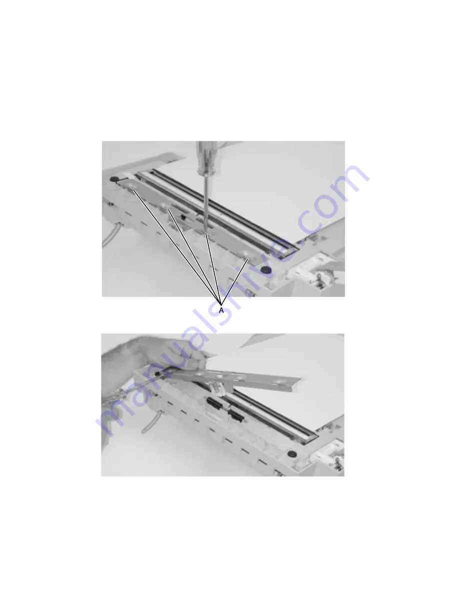
Internal ADF CCD subassembly
Warning: Screws for the CCD card in the optical unit are as shown in
“Charge-coupled device
(CCD) card screws” on page 3-5
. These screws have a red coating indicating they
should never be loosened.
1.
Remove the ADF drive motor. See
“ADF drive motor” on page 3-13
.
2.
Turn the ADF unit upside down.
3.
Remove the four screws from the lower ADF frame plate.
4.
Remove the ground screw.
5.
Remove the idler rollers.
Содержание 16C0365 - 5500 MFP
Страница 36: ...3 12 Service Manual 4036 402 7 Remove the ground screw and washer 8 Lift off the ADF lower guide ...
Страница 38: ...3 14 Service Manual 4036 402 4 Remove the three screws A securing the ADF drive motor 5 Remove the motor A ...
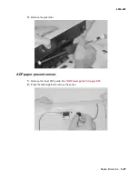
Страница 49: ...Repair information 3 25 4036 402 3 Remove the pick pad ...
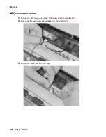
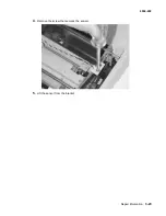
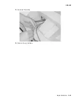
Страница 53: ...Repair information 3 29 4036 402 4 Remove the screw that secures the sensor 5 Lift the sensor from the bracket ...
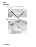
Страница 55: ...Repair information 3 31 4036 402 5 Disconnect the cables 6 Remove the user interface ...
Страница 57: ...Repair information 3 33 4036 402 4 Pull forward and upward to unlatch the housing Lift the housing off ...
Страница 68: ...3 44 Service Manual 4036 402 ...
Страница 69: ...Connector locations 4 1 4036 402 4 Connector locations Locations Paper path and sensors ...
Страница 70: ...4 2 Service Manual 4036 402 Internal view ...
Страница 76: ...5 4 Service Manual 4036 402 ...
Страница 78: ...6 2 Service Manual 4036 402 Assembly 1 Upper Scanner ...
Страница 80: ...6 4 Service Manual 4036 402 Assembly 2 Lower scanner 12 1 2 3 4 5 6 7 8 9 11 10 13 14 15 16 17 17 ...
Страница 86: ...I 4 Service Manual 4036 402 ...


