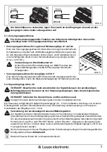
Leuze MSI 200 Скачать руководство пользователя страница 16

16

4. Installation 

WARNING: Danger!


Never carry out work when mains voltage is present !

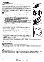
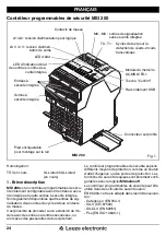
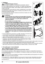
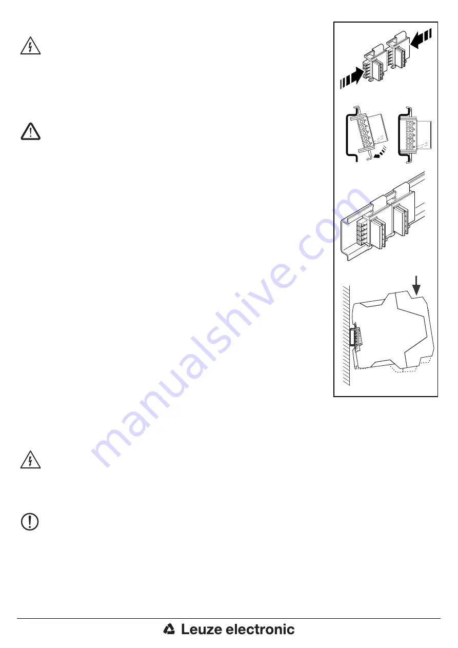
The MSI 200 programmable safety controller is equipped with two DIN rail 

connector interfaces on its mounting side for extension modules.

With the DIN rail connector, gateways for transmitting non-safe diagnostic 

values can be connected at the left of the safety module. 

The safe extension modules are connected at the right of the safety module. 
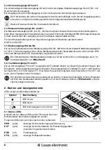
CAUTION: 

• You must use the yellow DIN rail connector


AC-MSI-TCS 

(Order No. 547821) for connecting the MSI 200 programmable 

safety controller and the safe extension modules. 

• Do not use a terminating connector.

• You must use the gray DIN rail connector AC-MSI-TC 

(Order No. 547823) for connecting standard extension 

modules (e.g. PROFIBUS gateways).

• Installing the devices on and removing them from the DIN rail 

connector is only permitted in a de-energized state.

• The safe extension modules have to be connected at the right 

of the safety controller.

• Standard extension modules must be installed on the 


left-hand side of the safety controller.

• When using DIN rail connectors, connect the required number together 

and push them onto the DIN rail. 

• When positioning the MSI 200, please ensure that it is aligned correctly 

with the DIN rail connector on the DIN rail.

• Place the yellow safety controller and the safe extension modules on the 

yellow DIN rail connectors and the gray extension modules on the gray DIN 

rail connectors.

• Plug the extension modules together in such a way that all non safety-ori-

ented gray modules are mounted to the left and all safety-oriented yellow 

modules are mounted to the right.

• Place the included quick-mounting end clamp at the right next to the last 

device of the MSI system. Thus accidentally connecting additional DIN rail connectors is prevented.
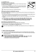
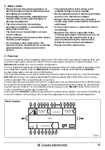
5. Connection notes

WARNING: Danger!

Never carry out work when mains voltage is present!

Generally speaking, there are a large number of applications which use multiple sensors or controlling 

devices. Depending on the size of the machine or system, a considerable amount of cabling may be 

required to wire the sensors. 

Make sure that the specified cable lengths are not exceeded, so as to ensure error-free operation 

of the safety circuit.

In order to comply with the UL, use copper cables that are designed for operating temperatures of 75°C. 

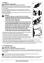
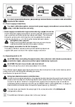
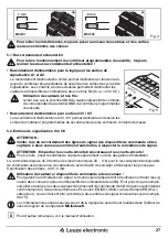
To ensure the contacts are reliable and touch proof, strip the cable ends as shown below (Fig. 4). 

C

C

A

A

B

B

D

Fig. 3

AC-MSI-TCS

AC-MSI-TC

Содержание MSI 200

Страница 1: ...bles de seguridad U S E R M A N U A L 2011 07 700930 We reserve the right to make technical changes MSI 200 DE Programmierbare Sicherheits Schaltger te EN Programmable Safety Controllers FR Contr leur...

Страница 2: ...3 Funktion 5 4 Montage 6 5 Anschlusshinweise 6 6 Bedien und Anzeigeelemente 6 1 Status LEDs 8 6 2 LEDs f r sichere Signaleing nge ausg nge 9 6 3 USB Schnittstelle 10 6 4 AC MSI CFG1 Datenspeicher Bau...

Страница 3: ...USB 40 6 4 AC MSI CFG1 modulo di memoria 40 6 5 Pulsante CONFIRM 41 7 Moduli di espansione protetti 41 8 Dati tecnici 42 1 Descripci n resumida 44 2 Indicaciones de seguridad 45 3 Funcionamiento 45 4...

Страница 4: ...ung f r Logik 24V 0V Ausgangsversor gungsspannung Masseschaltausg nge Tragschienen verbinder Zulassung 1 Kurzbeschreibung MSI 200 ist ein frei programmierbares Sicherheits Schaltger t mit 20 sicheren...

Страница 5: ...us tzliche sichere Erweiterungsmodule anreihen Auf der linken Seite k nnen Sie Bus Gateways zur nicht sicher heitsgerichteten Diagnose anreihen Beachten Sie die Sicherheitsvorschriften der Elektrotech...

Страница 6: ...des Tragschienenverbinders stecken Sie die ben tigte Anzahl zusammen und dr cken Sie diese in die Tragschiene Beachten Sie beim Aufsetzen des MSI 200 auf die Tragschiene die passende Ausrichtung zum...

Страница 7: ...ignalredun danz gew hrleisten VORSICHT Schlie en Sie Querschl sse und Kurzschl sse aus Verlegen Sie dazu die Sensorleitungen getrennt oder in Installationsrohren Die Steuerung verf gt ber 20 digitale...

Страница 8: ...t wie f r die sicheren Ein und Ausg nge auch im Verdrahtungseditor von MSIsafesoft 5 6 Testtaktausg nge T0 und T1 Die an den Ausg ngen T0 und T1 ausgegebenen Testtakte dienen zur Querschlusserkennnung...

Страница 9: ...ster am Ger t Normalbetrieb ohne angeschlossene Erweiterungsger te Kommunikation ber den Tragschienenverbinder Normalbetrieb mit angeschlossenen Erweiterungsger ten Kommunikation ber den Tragschienenv...

Страница 10: ...n Konfigurations PC m ssen Sie dort die ben tigten USB Treiber installieren Dazu erscheint der Assistent f r das Suchen neuer Hardware Auf die Abfrage soll eine Verbindung mit Windows Update hergestel...

Страница 11: ...ird Des weiteren ist es m glich einen bereits konfigurierten MSI 200 mittels eines Programmes auf einem Datenspeicher Baustein AC MSI CFG1 zu konfigurieren Die Vorgehensweise hierzu entnehmen Sie bitt...

Страница 12: ...ennungszeit bei 1 kanaliger Struktur 1 s Statusanzeige 20 LEDs gr n Ausgangsdaten Sichere Halbleiterausg nge 4 Kat 4 EN ISO 13849 1 EN 954 Masseschaltausg nge 2 Nennspannung 24 V DC 24 V 0 V Zul ssige...

Страница 13: ...egorie nach EN 954 1 4 Performance Level nach EN ISO 13849 1 e SILCL nach EN 62061 3 Safety Integrity Level SIL nach IEC 61508 3 Kenngr en nach EN ISO 13849 3 MTTFD Jahre 8321 high DC 99 high Kenngr e...

Страница 14: ...A2 Supply voltage for logic 24 V 0 V Output supply voltage Ground switching outputs DIN rail connector Approval 1 Short description MSI 200 is a freely programmable safety controller with 20 safe inpu...

Страница 15: ...by means of the DIN rail connector interface On the left you can connect bus gateways for non safety oriented diagnostics Please observe the safety regulations of electrical engineering and industrial...

Страница 16: ...ush them onto the DIN rail When positioning the MSI 200 please ensure that it is aligned correctly with the DIN rail connector on the DIN rail Place the yellow safety controller and the safe extension...

Страница 17: ...ensure that signal redundancy is present CAUTION Prevent cross circuits and short circuit To this end lay the sensor cables separately or in conduits The controller has 20 digital signal inputs I0 to...

Страница 18: ...s are linked in the connection editor of MSIsafesoft 5 6 Test pulse outputs T0 and T1 The test pulses output at outputs T0 and T1 are used for cross circuit detection at the inputs There are two of ea...

Страница 19: ...CONFIRM button on the device Normal operation with no extension devices connected DIN rail connector communication Normal operation with extension devices connected DIN rail connector communication Re...

Страница 20: ...you will need to install the required USB drivers on the PC The Found New Hardware wizard will appear in order to help you do this Select No not this time when the Can Windows connect to Windows Upda...

Страница 21: ...ton if this is indicated by the CFG LED flashing It is also possible to configure a previously configured MSI 200 using a program on an AC MSI CFG1 data memory module For details of this procedure ple...

Страница 22: ...Output data Safe semiconductor outputs 4 Cat 4 EN ISO13849 1 EN 954 Ground switching outputs 2 Nominal voltage 24 V DC 24 V 0 V Permissible range 0 85 1 1 x UN Limiting continuous current 2 A see der...

Страница 23: ...per EN 954 1 4 Performance level as per EN ISO 13849 1 e SILCL as per EN 62061 3 Safety Integrity Level SIL as per IEC 61508 3 Parameters as per EN ISO 13849 3 MTTFD years 8321 high DC 99 high Parame...

Страница 24: ...sortie Contacts de masse Connecteur sur profil Homologation 1 Br ve description MSI 200 est un contr leur programmables de s cu rit librement configurable avec 20 entr es s cu rit int gr e et quatre s...

Страница 25: ...ajout s sur le c t droit du MSI 200 par l interm diaire du connecteur sur profil Sur le c t gauche des passerelles de bus vers le diagnostic s curis peuvent tre raccord es Respecter les consignes de s...

Страница 26: ...cteur sur profil assembler le nombre requis de connecteur sur profil puis les presser dans le profil Tenir compte lors de la mise en place du MSI 200 sur le profil de l orien tation correcte par rappo...

Страница 27: ...ecter la redondance de signal ATTENTION Emp cher les courts circuits transversaux et les courts circuits Pour ce faire poser les c bles de capteurs s par ment ou dans des gaines d installation La comm...

Страница 28: ...ris es dans l diteur de liens du logiciel de configuration MSIsafesoft 5 6 Sorties du cycle de test T0 et T1 Les cycles de test au niveau des sorties T0 et T1 servent d tecter les courts circuits tran...

Страница 29: ...tif Fonctionnement normal sans dispositif d extension raccord communication sur connecteur sur profil Fonctionnement normal avec dispositifs d extension raccord s communication sur connecteur sur prof...

Страница 30: ...du premier raccordement du contr leur programmables de s curit MSI 200 au PC de configuration vous devez installer les pilotes USB requis Pour cela l assistant de recherche de nouveaux mat riels s aff...

Страница 31: ...au moyen d un programme sur un AC MSI CFG1 Pour en savoir plus sur cette proc dure consulter le manuel utilisateur Acquittement des messages d erreur affich s La touche CONFIRM permet d acquitter les...

Страница 32: ...rtie Sorties semi conducteurs s curis es 4 cat 4 EN 13849 1 EN 954 Contacts de masse 2 Tension nominale 24 V CC 24 V 0 V Plage admissible 0 85 1 1 x UN Intensit permanente limite 2 A cf D classement C...

Страница 33: ...EN 954 1 4 Niveau de performance selon EN ISO 13849 1 e SILCL selon CEI 62061 3 Niveau de s curit int gr e SIL selon CEI 61508 3 Caract ristiques selon EN ISO 13849 3 MTTFD ans 8321 high DC 99 high C...

Страница 34: ...one di alimenta zione in uscita Uscite di commutazione a massa Connettore per guide di supporto Omologazione 1 Descrizione sintetica MSI 200 uncontrolloredisicurezzacompletamente configurabile dotato...

Страница 35: ...r guide di supporto Sul lato sinistro possibile affiancare i gateway bus per la diagnosi non le gata alla sicurezza Attenersi alle norme di sicurezza previste dal settore elettrotecnico e dall associa...

Страница 36: ...e il nu mero di connettori necessari e spingerli all interno della guida Durante l installazione di MSI 200 sulla guida di montaggio controllare il corretto orientamento rispetto al connettore per gui...

Страница 37: ...i segnale ATTENZIONE Evitare qualsiasi possibilit di cortocircuiti e cortocircuiti trasversali A questo scopo posare i cavi dei sensori separatamente o in tubi di installazione L unit di controllo dis...

Страница 38: ...ingressi e le uscite protetti il collegamento delle uscite di segnalazione avviene nell editor di interconnessione di MSIsafesoft 5 6 Uscite di trigger per test T0 e T1 I cicli di test collegati alle...

Страница 39: ...namento normale senza moduli di espansione collegati comunicazione tra connettore per guide di supporto Funzionamento normale con moduli di espansione collegati comunicazione tra connettore per guide...

Страница 40: ...ollore programmabile di sicurezza MSI 200 al PC di configurazione ins tallare i driver USB necessari Per questa operazione si apre la Procedura guidata per la ricerca di nuovi hardware Alla richiesta...

Страница 41: ...gi e premere il pulsante CONFIRM inoltre possibile configurare un MSI 200 gi configurato tramite un programma su un modulo di memoria AC MSI CFG1 Per questa procedura consultare il manuale utente Rese...

Страница 42: ...di uscita Uscite semiconduttore protette 4 Cat 4 EN 13849 1 EN 954 Uscite di commutazione a massa 2 Tensione nominale 24 V DC 24 V 0 V Range ammesso 0 85 1 1 x UN Corrente limite permanente 2 A v dera...

Страница 43: ...i sicurezza Categoria a norma EN 954 1 4 Performance Level a norma EN ISO 13849 1 e SILCL a norma EN 62061 3 Safety Integrity Level SIL a norma IEC 61508 3 Dati tecnici a norma EN ISO 13849 3 MTTFD an...

Страница 44: ...las salidas Salidas de conmutaci n de masa Conector para carriles Homologaci n 1 Descripci n resumida MSI 200 es un controlador programable de seguri dad de configuraci n libre con 20 entradas segura...

Страница 45: ...el lado izquierdo podr Ud anexar las pasarelas de enlace de bus para el diag n stico no orientado a la seguridad Observe las prescripciones de seguridad de la electrot cnica y de la Berufsgenossen sc...

Страница 46: ...il ensamble la cantidad necesaria de conectores para carriles y enc jelos en el carril Al colocar el MSI 200 en el carril preste atenci n a que la orientaci n respecto al conector para carriles sea co...

Страница 47: ...tizar la redundancia de se ales PRECAUCI N Descarte toda posibilidad de cortocircuitos y derivaci n cruzada A tal efecto tienda los cables de los sensores separados o dentro de tubos de instalaci n El...

Страница 48: ...as entradas y salidas seguras las salidas de aviso se vinculan tambi n en el editor de circuitos de MSIsafesoft 5 6 Salidas de ciclos de prueba T0 y T1 Los ciclos de prueba emitidos en las salidas T0...

Страница 49: ...ato Servicio normal sin aparatos de ampliaci n conectados comunicaci n a trav s del conector para carriles Servicio normal con aparatos de ampliaci n conectados comunicaci n a trav s del conector para...

Страница 50: ...able de seguridad MSI 200 al PC de configuraci n deben instalarse en el PC los drivers USB necesarios Para esto se abre el Asistente de b squeda de hardware nuevo En la consulta desea establecer una c...

Страница 51: ...D CFG Tambi n es posible configurar un MSI 200 previamente configurado en un componente de memoria AC MSI CFG1 a trav s de un programa El procedimiento correspondiente se describe en el manual de usua...

Страница 52: ...erde Datos de salida Salidas seguras por semiconductor 4 cat 4 EN 13849 1 EN 954 Salidas de conmutaci n de masa 2 Tensi n nominal 24 V DC 24 V 0 V Margen admisible 0 85 1 1 x UN Corriente constante l...

Страница 53: ...6 Par metros t cnicos de seguridad Categor a seg n EN 954 1 4 Performance Level seg n EN ISO 13849 1 e SILCL seg n EN 62061 3 Safety Integrity Level SIL seg n IEC 61508 3 Par metros seg n EN ISO 13849...

Страница 54: ...54...

Страница 55: ...55...

Страница 56: ...2011 Leuze electronic GmbH Co KG In der Braike 1 D 73277 Owen Teck Germany Phone 49 7021 573 0 Fax 49 7021 573 199 http www leuze com info leuze de MNR 9056354 2011 07 01 Dok Nr 83123023 00...

Отзывы: