Electrical connection
Leuze electronic
CR 55
13
1
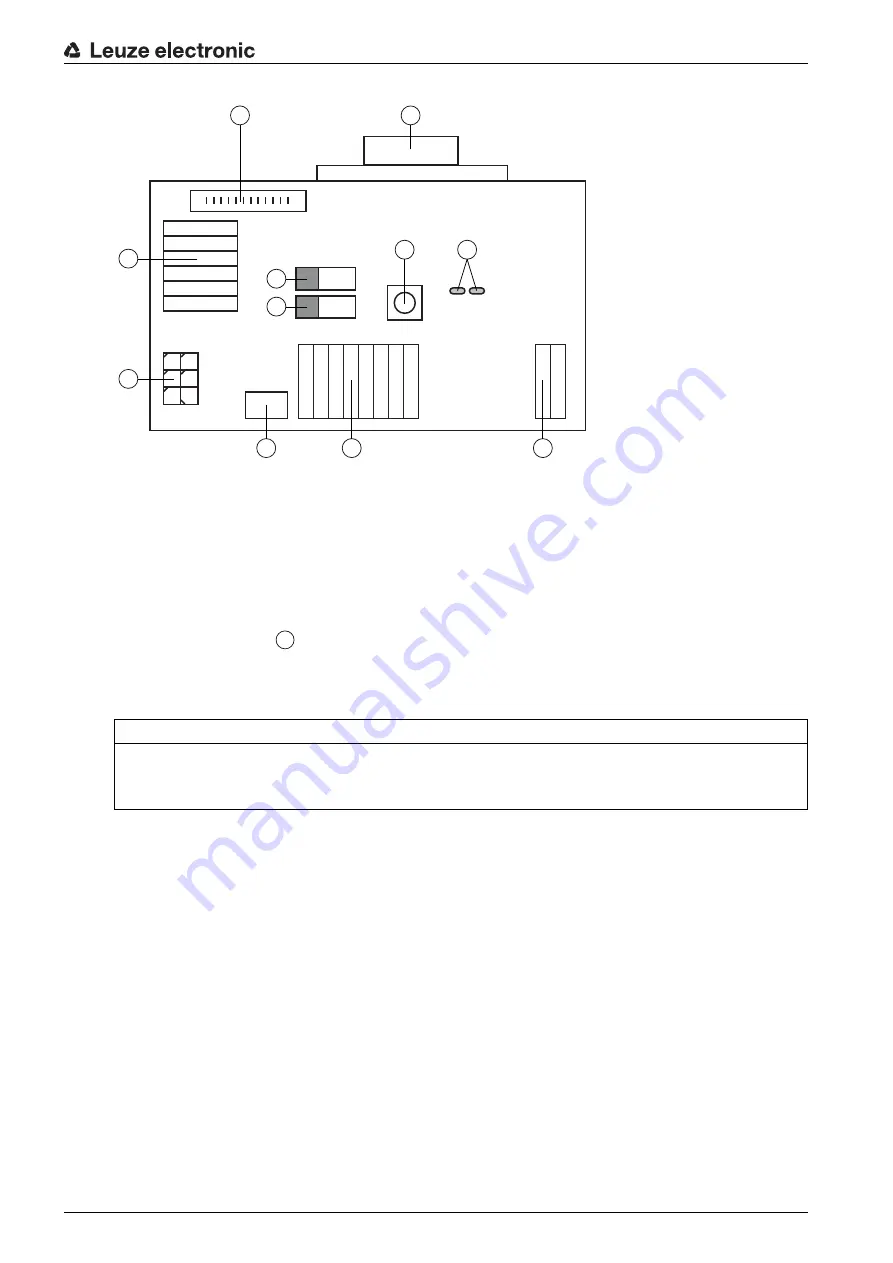
RS 232 connection
2
CR 50 connection
3
CR 100 or CR 55 connection
4
Molex Micro-Fit, 6-pin
5
USB connection
6
Connection to machine control, PLC, external voltage supply 5 VDC
7
External voltage supply 10 … 30 VDC
8
SWIN DIP switch (level for trigger button; 5 V if the scanner high switching input is active, GND if the
low input is active)
9
USB/PWR DIP switch (USB position if voltage is supplied via USB; PWR position if voltage is sup
-
plied via
)
10
Trigger button
11
Status LEDs
Figure 5.3: Connection options for MA-CR adapter circuit board
5.5
Cable lengths and shielding
The maximum cable length is 3 m.
Should a cable extension be necessary, make certain that the cables of the RS 232 interface are shielded.
NOTICE
Using the adapter circuit board
The MA-CR adapter circuit board is intended only for laboratory and test purposes and is not to be
used for industrial applications!
1
2
10
11
3
4
8
9
5
6
7
7


