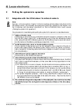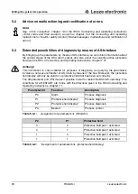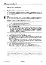
Construction, assembly and connection to power supply
Leuze electronic
RS4/AS-i
17
T
N
T
35/
7-
24V
DEUTSCH
ENGLISH
FRANÇAIS
IT
ALIANO
ESPAÑO
L
NEDERLANDS
4.3
Electrical connection
4.3.1
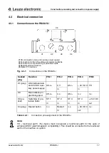
Connections on the RS4/AS-i
Note:
FE – functional earth. The device must incorporate a functional earth for the sake of
enhanced EMC (electromagnetic compatibility). This should be connected to the functional
earth of the machine or system.
Fig. 4.3-1:
Connections on the RS4/AS-i
Socket/
plug
Function
PIN 1
PIN 2
PIN 3
PIN 4
PIN 5
X1 (plug)
AS-Interface data
and 24 VDC auxi-
liary power supply
AS-i
+
0 V
AS-i
-
+ 24 V DC FE
in
in
X2
Bus address pro-
gramming input
AS-i
+
n.c.
AS-i
-
n.c.
n.c.
X3 (so-
cket)
Switching of pro-
tective fields
SF 1
SF 2
SF 3
SF 4
+ 24 V DC
in
in
in
in
out
X4 (plug)
Restart button
n.c.
Restart
n.c.
+ 24 V DC n.c.
in
out
Table 4.3-1:
Connection pin assignment of the RS4/AS-i
X1AS-i connection (data and auxiliary power supply)
X2Connection for the AS-i address programming device
X3Connection for the switching of protective fields
X4Restart button connection
X5Optical PC interface
X1
X2
X5
X4
X3


