


8
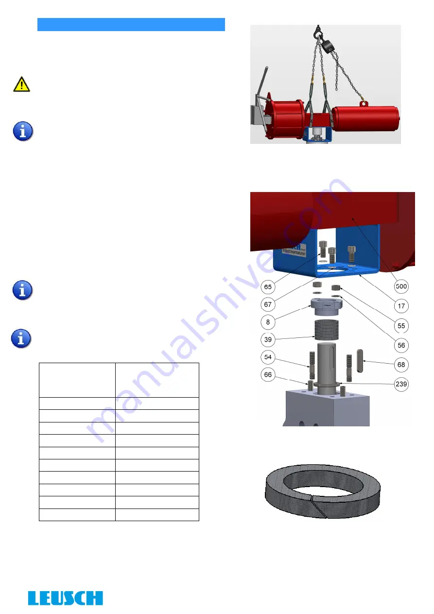
Replacement of the Gland Packing
(Fig. 8)
The numbers in square brackets e.g. [500] are item numbers
relating to the adjacent figures.
Prerequisite:
The complete section of the pipework in which the valve is
installed is de-pressurised, cleanse and easily accessible so
that the service personnel are not endangered in any way.
The actuator is free of connections so that it can be taken off
the valve and safely stored at another location. All figures are
only example illustrations for explanation.
1.
Secure the actuator [500] with the crane, as in (Fig.7)
2.
Loosen and remove the screws [65] and the washers
[67].
3.
Lift the actuator [500] with the crane and place in a
safe location.
4.
Remove the key [68].
5.
Loosen and remove the nuts [55] and the washers [56].
6.
Disassemble the gland [8] and remove the old packing
rings [39]. (The support ring [239] remains in the body.)
7.
Insert new packing rings [39] and position them.
8.
Install the gland [8], nuts [55] and washers [56].
9.
Tighten the nuts [55] alternately by hand using minimal
force.
10.
Install the key [68].
11.
Put the valve into operation and alternately tighten the
nuts [55] in little steps in the event of any leaks on the
packing [39]. It has to be ensured, that the gland is
always parallel to the body surface (Fig 5).
12.
Do not tighten the nuts [55] more than necessary.
The maximum torque in Table 1 on Page 8 must not
be exceeded.
13.
If there is still a leak, the manufacturer should be con-
tacted.
If the valve is fitted with an actuator which may not be re-
moved for technical reasons the filling of the gland can take
place as follows: Make a diagonal cut in the packing ring
(Fig.
9)
and feed the ring carefully over the shaft and into the gland.
When inserting the packing rings, watch out that the interfaces
of the individual rings do not lie on top of each other.
Do not exceed the thread tightening torques from Table 1 be-
low.
Fig. 7
Fig. 8
Fig. 9
Thread sizes
Max. allowable torque [Nm]
M6
9,1
M8
21,8
M10
44
M12
75
M16
180
M20
370
M24
608
M27
421
M30
571
M33
779
Table 1
(Values in the table are applicable for lubricated threads)