background image

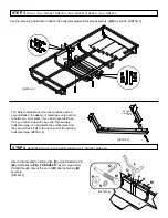
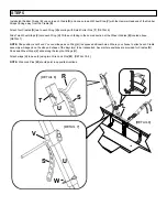
One Cradle assembly should be attached 

to each side of each Wing [

U

] as 

instructed in STEP 5. 

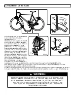
Lift the bicycle and hang it on the Rack-IT 

with the drive-train of the bicycle facing 

away from the rack for a closer fit. Secure 

each wheel to Cradles [

R

] as shown 

[DETAILS 9]. Loosen and adjust Wheel 

Stops [

V

] until they are flush and resting 

against the bottom of the tire [DETAIL 10]. 

[Removing the Wing [

U

] and rearranging 

the Wheel Stops [

V

] and Wheel Cradles 

[

R

] may be necessary depending on your 

bicycles size and style.] Once the Cradles 

[

R

] and Wheel Stops [

V

] have been fit to 

size, stretch the adjustable Rubber Straps 

[

S

] over the tire and reconnect to the 

hole position the is one hole tighter than 

necessary with the wheel sandwiched at the end of the Pegs of the away from the Wing [

U

] [DETAIL 11].

Note: Bike Tire can be adjusted in and out to remove contact with the Rack-IT. The pads should be positioned as 

necessary for added protection to the finish of the bicycle. 

To attach a second bicycle follow the same procedure using the two remaining cradles [

R

] and wheel stops [

V

] attached 

to the back side of the Wings [

U

]. Position the second bicycle with the handlebars towards the back of the first bicycle. 

ATTACHMENT OF BICYCLES

RUBBER 

STRAP

CRADLE

BICYCLE

WHEEL

DETAIL 9

DETAIL 10

DETAIL 11

CRADLE

RUBBER 

STRAP

RUBBER 

STRAP

RUBBER 

STRAP

BICYCLE

WHEEL

WHEEL

STOP

      WARNING:


IMPORTANT FOR SAFETY!  AFTER ATTACHING BICYCLE(S), 

BUT BEFORE DRIVING THE VEHICLE, DOUBLE CHECK ALL 

POINTS OF ATTACHMENT TO BE SURE THAT THEY ARE 

TIGHT AND SECURE!

Содержание Rack-IT H01199

Страница 1: ... MOTION PIN N 1 LOCK WASKER P 1 1 2 FLAT WASHER Q 1 LARGE COTTER PIN R 4 WHEEL CRADLES S 8 RUBBER STRAPS T 4 SMALL COTTER PIN U 2 WINGS V 4 WHEEL STOPS W 2 WIRE LOCK PINS STEP 2 TOOLS 4mm ALLEN WRENCH Attach angel bracket K as shown Do so by removing the two joint connector bolts from the side tube of the GearCage hitch carrier GearCage not included posi tioning the angel bracket K as shown then r...

Страница 2: ...GearCage cargo carrier to hold even more bikes If you add a second Rack It kit you will end up with one extra throw away horizontal pipe You will attach the vertical pipe from the second Rack It kit to the open end of the existing horizontal pipe DETAIL 4 STEP 4 REQUIRED TOOLS 9 16 SOCKET WRENCH 3 4 SOCKET WRENCH L M M N N P P Q Q Attach V Brace A to Vertical Pipe B using No Motion Pin M and Washe...

Страница 3: ...ach Wing U With each facing in the same direction at the Wheel Cradles R located above DETAIL 7 NOTE Pad position is not fixed You can slide pads on Wing U to expose additional holes Where you choose to attach each Cradle assembly will depend on the size and shape of the bicycle s to be transported Several hole positions are provided for Cradles R Pads and Wheel Stops V slide along the length of W...

Страница 4: ... the is one hole tighter than necessary with the wheel sandwiched at the end of the Pegs of the away from the Wing U DETAIL 11 Note Bike Tire can be adjusted in and out to remove contact with the Rack IT The pads should be positioned as necessary for added protection to the finish of the bicycle To attach a second bicycle follow the same procedure using the two remaining cradles R and wheel stops ...

Страница 5: ... thereof found to be defective within that period will be replaced without charge provided that 1 the product was not misused 2 no alterations or modifications were made 3 its failure was not a result of normal wear expected in the use of the product 4 the product or part is delivered freight prepaid to Let s Go Aero Manufacturers only obligation shall be to replace such products or parts proved t...

Отзывы: