


should not be subject to vibrations.
The seals should be able to withstand the
forces engaged during normal motor operation,
as well as a possible over-torque of 2.5 times
the rated torque.
If atmospheric pollution is a problem the
following solutions are available : air filter,
ducting of cables, etc: see technical catalogue
ref. 1337… pages 50 & 80 for cooling methods,
page 129 for options.
The motor terminals and inspection doors
should be easily accessible to facilitate repairs
and maintenance.
Connection
See section
4.1 page 2 of the general
manual.
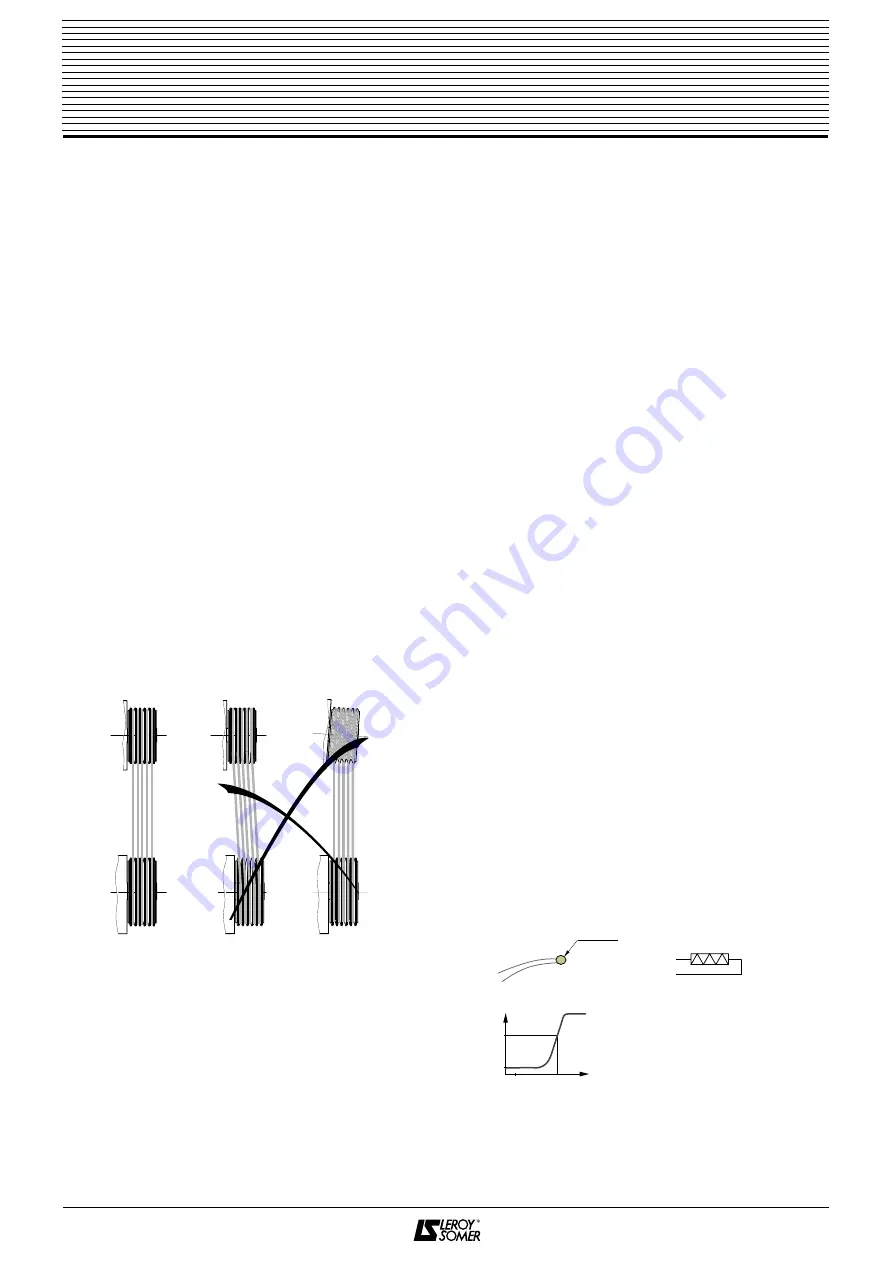
Check the connections are correctly aligned
(see figure 5).
For pulley and belt installations, compatilibity
of the forces (radial and axial) exerted on the
shaft MUST be compared to those listed in
the relevant sections of the technical
catalogue reference 1337.
For sleeve couplings a sufficient gap should
be left between the two coupling halves to
allow thermal expansion without axial thrust.
Do not use tools which jolt or bang the motor
as this may damage the bearings.
6. - ELECTRICAL CONNECTION
See section 4.2 page 3 of the general manual. Re-
fer to the diagrams for details on how to connect
the motor.
In the motor power circuit we recommend that
there is :
-
thermal protection by integration of overload
(100% of supply current);
-
instantaneous protection (200% of supply
current);
- protection against ground faults;
- protection against field overvoltages: if there is a
short-circuit in the field coil supply, place a resistor
R
p
in parallel with the field coil. For example :
R
p
= 800
x
U
exc
/ P
exc
where
R
p
parallel resistance in
Ω
,
U
exc
field voltage in V,
P
exc
field power supply in W.
Do not forget to connect the earth terminal to earth.
6.1 - Thermal detection
If a shorter protection reaction time is required, or
if you want to detect transient overloads and
monitor temperature rises at "hot spots" in the
motor or at strategic measured points in the
installation for maintenance purposes, installation
of heat sensors at "sensitive" points is
recommended. The various types are described
below.
NB : Heat sensors do not themselves protect the
motor.
Motors can be fitted with the following types of
thermal detector :
• thermistor (PTC probe : diag. 6)
These are thermovariable resistors with positive
temperature coefficients (marked with black flag-
type labels -trip- or blue -alarm-). When there is
an increase in temperature, the probe resistance
increases slowly then very quickly within a range
of
±
5
°
C of the nominal running temperature
(NRT).
The resistance value measured
at R terminals must be less
than 250
Ω
at the ambient tem-
perature.
Max. voltage : 2.5 V per probe.
4
LSK
D.C. motors
☞
Fig. 5
Ø ~3 mm
Fig. 6
R
NRT
T
0
250
1350
Ω
20
°C


