


Mechanical installation
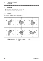
Mounting of g500 short/servo adapters with clamping connection
Mounting the gearboxes
20
Lenze ¯ MA 12.0018 ¯ 2.0
8
7
2
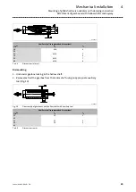
Fig. 5
Assignment: Motor shaft, clamping ring and mounting hole
2
Bell housing
7
Clamping ring
8
Terminal screw
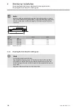
4. Afterwards, insert the wrench (9) into the terminal screw (8) of the clamping ring
(7) and leave it there (Fig. 6). The terminal screw (8) must only be tightened to
such a degree that the clamping ring (7) does not move but the shaft is not
tightened yet!
1.
3.
2.
1
9
3
Fig. 6
Mounting of motor and gearbox
1
Gearbox
9
Wrench
3
Motor
Stop!
If the motor shaft is provided with a keyway, align the motor shaft in
such a way that the keyway is located opposite to the terminal screw.
Содержание g500 Series
Страница 38: ...Maintenance Maintenance operations 6 38 Lenze MA 12 0018 2 0 Form template dipsticks for G50BS122 A B C D E F...
Страница 39: ...Maintenance Maintenance operations 6 39 Lenze MA 12 0018 2 0 Form template dipsticks for G50BS140 A B C D E F...
Страница 40: ...Maintenance Maintenance operations 6 40 Lenze MA 12 0018 2 0 Form template dipsticks for G50BS166 C B D F A E...
Страница 43: ...Notes 43 Lenze MA 12 0018 2 0...


