


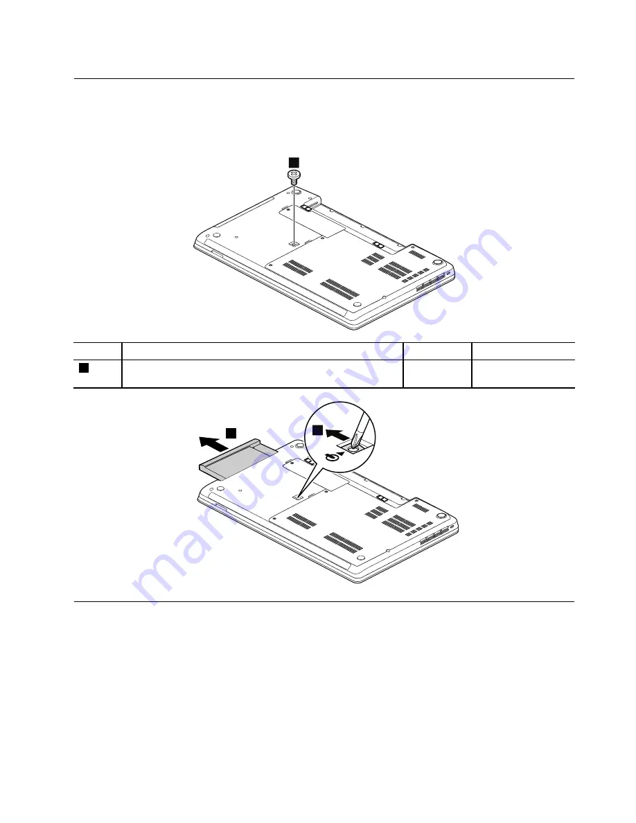
1040 Optical drive or blank bezel
For access, remove these FRUs in order:
•
“1010 Battery pack” on page 62
Removal steps of optical drive or blank bezel
1
Step
Screw (quantity)
Color
Torque
1
M2 × 3 mm, wafer-head, nylon-coated (1)
Black
0.181 Nm
(1.85 kgf-cm)
2
3
1050 Memory modules
For access, remove these FRUs in order:
•
“1010 Battery pack” on page 62
•
“1020 Large bottom cover” on page 63
Chapter 9
.
Removing or replacing a FRU
65
Содержание ThinkPad Edge E530
Страница 1: ...Hardware Maintenance Manual ThinkPad Edge E530 E530c and E535 ...
Страница 6: ...iv Hardware Maintenance Manual ...
Страница 11: ...DANGER DANGER DANGER DANGER DANGER DANGER Chapter 1 Safety information 5 ...
Страница 12: ...DANGER 6 Hardware Maintenance Manual ...
Страница 13: ...PERIGO PERIGO PERIGO Chapter 1 Safety information 7 ...
Страница 14: ...PERIGO PERIGO PERIGO PERIGO PERIGO 8 Hardware Maintenance Manual ...
Страница 15: ...DANGER DANGER DANGER DANGER DANGER Chapter 1 Safety information 9 ...
Страница 16: ...DANGER DANGER DANGER VORSICHT VORSICHT 10 Hardware Maintenance Manual ...
Страница 17: ...VORSICHT VORSICHT VORSICHT VORSICHT VORSICHT VORSICHT Chapter 1 Safety information 11 ...
Страница 18: ...12 Hardware Maintenance Manual ...
Страница 19: ...Chapter 1 Safety information 13 ...
Страница 20: ...14 Hardware Maintenance Manual ...
Страница 21: ...Chapter 1 Safety information 15 ...
Страница 22: ...16 Hardware Maintenance Manual ...
Страница 24: ...18 Hardware Maintenance Manual ...
Страница 25: ...Chapter 1 Safety information 19 ...
Страница 26: ...20 Hardware Maintenance Manual ...
Страница 27: ...Chapter 1 Safety information 21 ...
Страница 28: ...22 Hardware Maintenance Manual ...
Страница 48: ...42 Hardware Maintenance Manual ...
Страница 62: ...56 Hardware Maintenance Manual ...
Страница 101: ...In step 3 release the wireless antenna cables from the cable guides 3 3 Chapter 9 Removing or replacing a FRU 95 ...
Страница 102: ...In step 5 release wireless antenna cables from the cable guides 5 5 5 6 6 96 Hardware Maintenance Manual ...
Страница 108: ...2 2 3 4 5 When installing Make sure that the LCD connector is attached firmly 102 Hardware Maintenance Manual ...
Страница 113: ...a b c d Note Your model might not have the wireless WAN antenna assembly Chapter 9 Removing or replacing a FRU 107 ...
Страница 114: ...108 Hardware Maintenance Manual ...
Страница 117: ......
Страница 118: ...Part Number 0B48439_01 Printed in China 1P P N 0B48439_01 1P0B48439_01 ...


