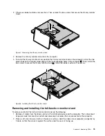


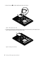


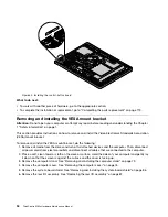


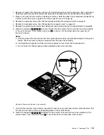

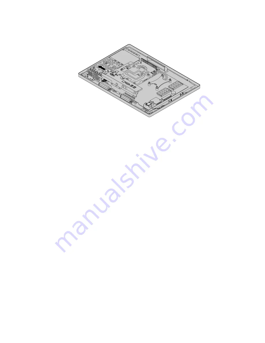
7. Remove the power cord connector from the rear I/O assembly.
Figure 23. Removing the power cord connector
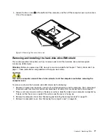
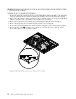
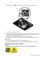
8. Disconnect the serial-connector cable and the PS/2 keyboard/mouse cable (if necessary) from the
system board. Then, remove the rear I/O assembly from the chassis.
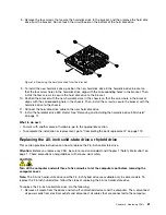
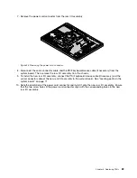
9. To install the new rear I/O assembly, connect the PS/2 keyboard/mouse cable (if necessary) and the
serial-connector cable of the new rear I/O assembly to the system board. See “Locating parts on the
system board” on page 71.
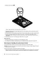
10. Note the orientation of the power cord connector and install it onto the new rear I/O assembly. Ensure
that the two screw holes in the power cord connector align with the corresponding holes in the new
rear I/O assembly.
Chapter 8
.
Replacing FRUs
89
Содержание ThinkCentre M83z
Страница 1: ...ThinkCentre M83z Hardware Maintenance Manual Machine Types 10C2 and 10C3 ...
Страница 6: ......
Страница 13: ...Chapter 1 Safety information 7 ...
Страница 17: ...Chapter 1 Safety information 11 ...
Страница 18: ...1 2 12 ThinkCentre M83z Hardware Maintenance Manual ...
Страница 19: ...1 2 Chapter 1 Safety information 13 ...
Страница 24: ...1 2 18 ThinkCentre M83z Hardware Maintenance Manual ...
Страница 25: ...1 2 Chapter 1 Safety information 19 ...
Страница 28: ...22 ThinkCentre M83z Hardware Maintenance Manual ...
Страница 32: ...26 ThinkCentre M83z Hardware Maintenance Manual ...
Страница 58: ...52 ThinkCentre M83z Hardware Maintenance Manual ...
Страница 64: ...58 ThinkCentre M83z Hardware Maintenance Manual ...
Страница 70: ...64 ThinkCentre M83z Hardware Maintenance Manual ...
Страница 75: ...Figure 3 Locating major FRUs and CRUs Chapter 7 Locations 69 ...
Страница 78: ...72 ThinkCentre M83z Hardware Maintenance Manual ...
Страница 126: ...120 ThinkCentre M83z Hardware Maintenance Manual ...
Страница 136: ...130 ThinkCentre M83z Hardware Maintenance Manual ...
Страница 137: ......
Страница 138: ......