

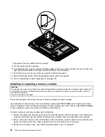


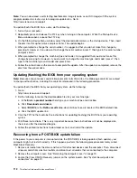


3. Lower and position the computer cover into place and then tighten the two screws
1
to secure the
computer cover.
Figure 50. Installing the computer cover
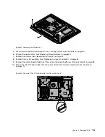
4. Reinstall the system stand and system stand hinge cover. See “Removing and reinstalling the system
stand” on page 73 and “Removing and reinstalling the system stand hinge cover” on page 71.
5. Lock the computer cover if you have an integrated cable lock.
6. Reconnect the external cables and power cord to the computer.
7. Depending on the parts you installed or replaced, you might need to confirm the updated information in
the Setup Utility program. Refer to Chapter 6 “Using the Setup Utility program” on page 53.
Note:
In most areas of the world, Lenovo requires the return of the defective Customer Replaceable Unit
(CRU). Information about this will come with the CRU or will come a few days after the CRU arrives.
110
ThinkCentre Hardware Maintenance Manual
Содержание ThinkCentre M72z
Страница 2: ......
Страница 8: ...2 ThinkCentre Hardware Maintenance Manual ...
Страница 15: ...Chapter 2 Safety information 9 ...
Страница 16: ... 18 kg 37 lbs 32 kg 70 5 lbs 55 kg 121 2 lbs 1 2 PERIGO 10 ThinkCentre Hardware Maintenance Manual ...
Страница 19: ...Chapter 2 Safety information 13 ...
Страница 20: ...1 2 14 ThinkCentre Hardware Maintenance Manual ...
Страница 21: ...Chapter 2 Safety information 15 ...
Страница 27: ...Chapter 2 Safety information 21 ...
Страница 31: ...Chapter 2 Safety information 25 ...
Страница 38: ...32 ThinkCentre Hardware Maintenance Manual ...
Страница 68: ...62 ThinkCentre Hardware Maintenance Manual ...
Страница 71: ...6 PS 2 mouse connector optional 13 USB connector USB port 1 7 Serial port Chapter 8 Locations 65 ...
Страница 73: ...Figure 3 Locating major FRUs and CRUs Chapter 8 Locations 67 ...
Страница 83: ...Figure 12 Removing the frame stand Chapter 9 Replacing FRUs 77 ...
Страница 120: ...114 ThinkCentre Hardware Maintenance Manual ...
Страница 125: ......
Страница 126: ......