
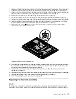


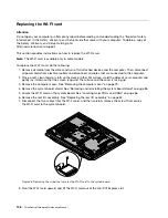


10. Route the new integrated camera cable, and then connect the integrated camera cable to the system
board. See “System board parts and connectors” on page 70.
11. Reinstall the system board shield. See “Removing and reinstalling the system board shield” on page 86.
12. Go to “Completing the parts replacement” on page 109.
Replacing the system board
Attention
Do not open your computer or attempt any repair before reading and understanding the “Important safety
information” in the
Safety , Warranty, and Setup Guide
that came with your computer. To obtain a copy of
the
Safety , Warranty, and Setup Guide
, go to:
http://www.lenovo.com/support
This section provides instructions on how to replace the system board.
To replace the system board, do the following:
1. Remove all media from the drives and turn off all attached devices and the computer. Then, disconnect
all power cords from electrical outlets and disconnect all cables that are connected to the computer.
2. Place a soft, clean towel or cloth on the desk or other flat surface. Hold the sides of your computer and
gently lay it down so that the screen is against the surface and the cover is facing up.
3. Remove the computer cover. See “Removing the computer cover” on page 79.
4. Remove the system board shield. See “Removing and reinstalling the system board shield” on page 86.
5. Locate the system board in the computer. See “Locating major FRUs and CRUs” on page 66.
6. Remove the heat sink assembly. See “Replacing the heat sink assembly” on page 89.
7. Remove the microprocessor. See “Replacing the microprocessor” on page 91.
8. Remove the memory modules. See “Installing or replacing a memory module” on page 98.
9. Remove the battery. See “Replacing the battery” on page 96.
10. Remove the rear I/O assembly to gain access to the system board. See “Replacing the rear I/O
assembly” on page 84.
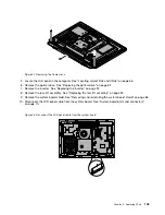
11. Note the locations of all cable connections on the system board and disconnect all cables. See “System
board parts and connectors” on page 70.
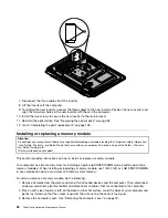
12. Remove the seven screws that secure the system board to the main bracket. Carefully lift the system
board out of the chassis.
102
ThinkCentre Hardware Maintenance Manual
Содержание ThinkCentre M72z
Страница 2: ......
Страница 8: ...2 ThinkCentre Hardware Maintenance Manual ...
Страница 15: ...Chapter 2 Safety information 9 ...
Страница 16: ... 18 kg 37 lbs 32 kg 70 5 lbs 55 kg 121 2 lbs 1 2 PERIGO 10 ThinkCentre Hardware Maintenance Manual ...
Страница 19: ...Chapter 2 Safety information 13 ...
Страница 20: ...1 2 14 ThinkCentre Hardware Maintenance Manual ...
Страница 21: ...Chapter 2 Safety information 15 ...
Страница 27: ...Chapter 2 Safety information 21 ...
Страница 31: ...Chapter 2 Safety information 25 ...
Страница 38: ...32 ThinkCentre Hardware Maintenance Manual ...
Страница 68: ...62 ThinkCentre Hardware Maintenance Manual ...
Страница 71: ...6 PS 2 mouse connector optional 13 USB connector USB port 1 7 Serial port Chapter 8 Locations 65 ...
Страница 73: ...Figure 3 Locating major FRUs and CRUs Chapter 8 Locations 67 ...
Страница 83: ...Figure 12 Removing the frame stand Chapter 9 Replacing FRUs 77 ...
Страница 120: ...114 ThinkCentre Hardware Maintenance Manual ...
Страница 125: ......
Страница 126: ......