14. Install the new system board into the chassis by aligning the eight mounting studs in the chassis with the
corresponding holes in the new system board. Carefully slide the new system board into the chassis until
it is secured in place by the mounting studs. Then, install the eight screws to secure the system board.
15. Install the battery back to the system board. See “Replacing the battery” on page 80.
16. Install the heat sink and fan assembly and connect the heat sink and fan assembly cable to the new
system board. See “Replacing the heat sink and fan assembly” on page 84.
17. Install all memory modules and PCI cards removed from the failing system board on the new system
board. See “Installing or replacing a memory module” on page 78 and “Installing or replacing a PCI
card” on page 75.
18. Reconnect all remaining cables to the system board. See “Locating parts on the system board”
on page 70.
19. Reinstall the front bezel. See “Removing and reinstalling the front bezel” on page 73.
20. Reinstall the computer cover.
21. Go to “Completing the parts replacement” on page 98.
The failing system board must be returned with a microprocessor socket cover to protect the pins during
shipping and handling.
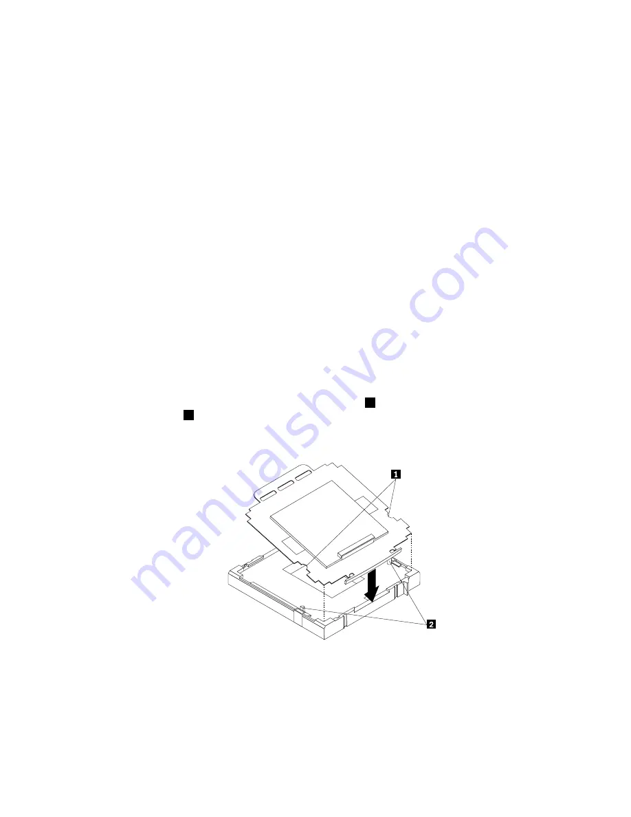
To install the microprocessor socket cover, do the following:
1. Release the lever securing the microprocessor retainer and open the retainer to access the
microprocessor.
2. Grasp the microprocessor on the sides and lift it straight up and out of the socket. Do not touch the
contacts on the microprocessor socket.
3. Note the orientation of the socket cover. Align the notches
1
of the microprocessor socket cover with
the alignment keys
2
of the microprocessor socket.
4. Install one side of the socket cover into the microprocessor socket as shown.
Figure 33. Installing the socket cover
Note:
Your microprocessor socket and cover might look slightly different from the illustration.
5. Carefully press the other side of the socket cover downwards until the socket cover snaps into place.
Chapter 8
.
Installing or replacing hardware: 0041, 0107, 0163, and 7543
97
Содержание ThinkCentre A85
Страница 1: ...ThinkCentre Hardware Maintenance Manual Machine Types 0041 0104 0107 0154 0163 7539 7543 and 7548 ...
Страница 2: ......
Страница 3: ...ThinkCentre Hardware Maintenance Manual Machine Types 0041 0104 0107 0154 0163 7539 7543 and 7548 ...
Страница 8: ...vi ThinkCentre Hardware Maintenance Manual ...
Страница 17: ...Chapter 2 Safety information 9 ...
Страница 18: ... 18 kg 37 lbs 32 kg 70 5 lbs 55 kg 121 2 lbs 1 2 PERIGO 10 ThinkCentre Hardware Maintenance Manual ...
Страница 21: ...Chapter 2 Safety information 13 ...
Страница 22: ...1 2 14 ThinkCentre Hardware Maintenance Manual ...
Страница 23: ...Chapter 2 Safety information 15 ...
Страница 29: ...Chapter 2 Safety information 21 ...
Страница 33: ...Chapter 2 Safety information 25 ...
Страница 40: ...32 ThinkCentre Hardware Maintenance Manual ...
Страница 74: ...66 ThinkCentre Hardware Maintenance Manual ...
Страница 108: ...100 ThinkCentre Hardware Maintenance Manual ...
Страница 148: ...140 ThinkCentre Hardware Maintenance Manual ...
Страница 243: ...Windows Vista Business 32 Recovery CD CRU MT 7548 Chapter 10 FRU lists 235 ...
Страница 244: ...236 ThinkCentre Hardware Maintenance Manual ...
Страница 248: ...240 ThinkCentre Hardware Maintenance Manual ...
Страница 257: ......
Страница 258: ...Part Number 0A23326 Printed in USA 1P P N 0A23326 0A23326 ...


