5.
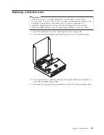
Remove
the
memory
module
being
replaced
by
opening
the
retaining
clips
as
shown.
6.
Position
the
replacement
memory
module
over
the
memory
connector.
Make
sure
the
notch
1
on
the
memory
module
aligns
correctly
with
the
connector
key
2
on
the
system
board.
Push
the
memory
module
straight
down
into
the
connector
until
the
retaining
clips
close.
7.
Reinstall
the
PCI
riser
assembly
and
adapters.
8.
Go
to
“Completing
the
FRU
replacement”
on
page
114.
Chapter
8.
Replacing
FRUs
87
Содержание ThinkCentre A55
Страница 1: ...Hardware Maintenance Manual Types 9636 9638 9640 9641 9642 9643 9644 9645 ...
Страница 2: ......
Страница 3: ...Hardware Maintenance Manual ...
Страница 6: ...Appendix Notices 201 Television output notice 202 Trademarks 202 iv Hardware Maintenance Manual ...
Страница 16: ...10 Hardware Maintenance Manual ...
Страница 17: ...Chapter 2 Safety information 11 ...
Страница 18: ... 18 kg 37 lbs 32 kg 70 5 lbs 55 kg 121 2 lbs 1 2 12 Hardware Maintenance Manual ...
Страница 22: ...16 Hardware Maintenance Manual ...
Страница 23: ...1 2 Chapter 2 Safety information 17 ...
Страница 24: ...18 Hardware Maintenance Manual ...
Страница 25: ...1 2 Chapter 2 Safety information 19 ...
Страница 32: ...26 Hardware Maintenance Manual ...
Страница 33: ...Chapter 2 Safety information 27 ...
Страница 34: ...1 2 28 Hardware Maintenance Manual ...
Страница 38: ...32 Hardware Maintenance Manual ...
Страница 39: ...1 2 Chapter 2 Safety information 33 ...
Страница 54: ...48 Hardware Maintenance Manual ...
Страница 102: ...96 Hardware Maintenance Manual ...
Страница 115: ...Chapter 8 Replacing FRUs 109 ...
Страница 122: ...116 Hardware Maintenance Manual ...
Страница 206: ...200 Hardware Maintenance Manual ...
Страница 209: ......
Страница 210: ...Part Number 42Y4652 Printed in USA 1P P N 42Y4652 ...


