1. Remove all media from the drives and turn off all attached devices and the computer. Then, disconnect
all power cords from electrical outlets and disconnect all cables that are connected to the computer.
2. Remove the computer cover. See “Removing the computer cover” on page 14.
3. Remove the front bezel. See “Removing and reinstalling the front bezel” on page 15.
4. Pivot the drive bay assembly upward to gain access to the front fan assembly. See “Accessing the
system board components and drives” on page 16.
5. Remove the hard disk drive for easier access to the front fan assembly. See “Replacing the hard
disk drive” on page 35.
6. Remove the heat sink fan duct. See “Replacing the power supply assembly” on page 28.
7. Note the cable routing and disconnect the front fan assembly cable from the system fan connector on
the system board. See “Locating parts on the system board” on page 9.
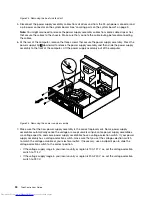
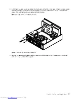
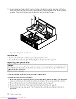
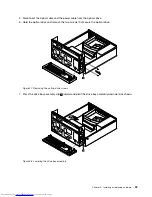
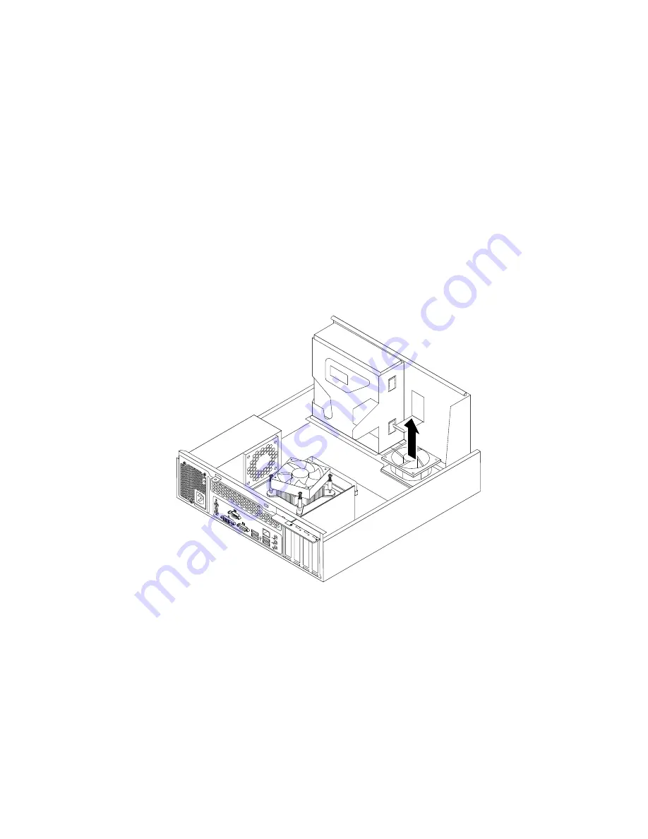
8. The front fan assembly is attached to the chassis by four rubber mounts. Remove the front fan assembly
by cutting the rubber mounts and lifting the front fan assembly out of the chassis.
Note:
The new front fan assembly will have four new rubber mounts attached.
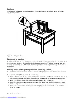
Figure 38. Removing the front fan assembly
40
ThinkCentre User Guide
Содержание ThinkCentre 7539
Страница 1: ...ThinkCentre User Guide Machine Types 0104 0154 7539 and 7548 ...
Страница 2: ......
Страница 3: ...ThinkCentre User Guide Machine Types 0104 0154 7539 and 7548 ...
Страница 8: ...vi ThinkCentre User Guide ...
Страница 20: ...12 ThinkCentre User Guide ...
Страница 56: ...48 ThinkCentre User Guide ...
Страница 70: ...62 ThinkCentre User Guide ...
Страница 74: ...66 ThinkCentre User Guide ...
Страница 84: ...76 ThinkCentre User Guide ...
Страница 85: ......
Страница 86: ...Part Number 0A22638 Printed in USA 1P P N 0A22638 0A22638 ...

