


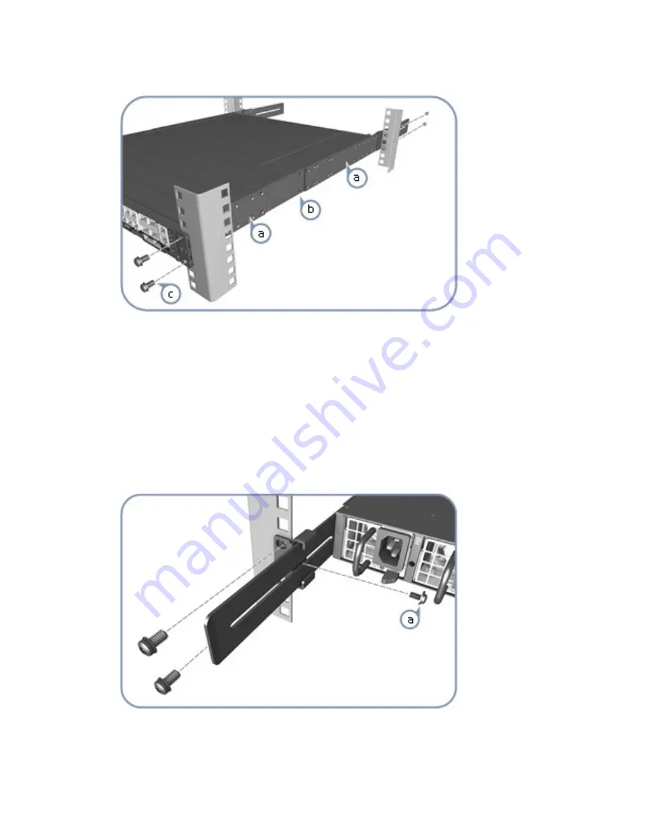
Step 2. Attach the brackets.
CAUTION:
Installing the switch in a rack requires two people. One person should position the
interconnect switch in the rack, while the other secures it using the rack screws.
a. Attach each of the rails to the interconnect switch using four of the included rail screws.
b. Use an additional two screws to secure each of the rails at the midpoint on the sides of the
interconnect switch.
c. Use the screws and cage nuts supplied with the rack to secure the switch in the rack.
Note:
Make sure that you attach the cage nuts to the rack before installing the interconnect switch.
Step 3. Adjust the rear-post rail flange and then lock the position of the rear-post rail flange using the
included position-locking screws.
Note:
You can also adjust the rear-post rail flange to fit different rack depths from 56 cm to 75 cm.
.
39
Содержание ThinkAgile CP 4000 Series
Страница 1: ...Lenovo ThinkAgile CP Hardware Installation Guide Models CP4000 CP6000 ...
Страница 4: ...ii Lenovo ThinkAgile CP Hardware Installation Guide ...
Страница 6: ...iv Lenovo ThinkAgile CP Hardware Installation Guide ...
Страница 8: ...vi Lenovo ThinkAgile CP Hardware Installation Guide ...
Страница 26: ...18 Lenovo ThinkAgile CP Hardware Installation Guide ...
Страница 70: ...Figure 42 X Link option 1 topology 62 Lenovo ThinkAgile CP Hardware Installation Guide ...
Страница 73: ...Figure 44 X Link topology option 2A Chapter 3 ThinkAgile CP Setup 65 ...
Страница 78: ...70 Lenovo ThinkAgile CP Hardware Installation Guide ...
Страница 80: ...72 Lenovo ThinkAgile CP Hardware Installation Guide ...
Страница 82: ...74 Lenovo ThinkAgile CP Hardware Installation Guide ...
Страница 83: ......
Страница 84: ......


