background image

6.

Wait 30 seconds for the UPS to stop functioning. Check the UPS display panel
to verify that the UPS is not functional.

7.

Remove the access cover on the terminal block cover and use a voltmeter to
ensure that hazardous voltage is no longer present.

Important:

Proceed only when no hazardous voltage is present on any

terminal.

8.

Unlock the conduit from the UPS terminal block cover. Then, loosen the set
screws holding the cable wires in the terminal block, and remove the cables.

9.

Connect the just-exposed wires together to help prevent exposure to
hazardous voltage.

10.

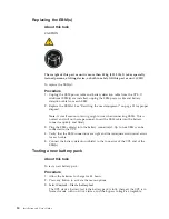
Remove the UPS battery pack by following the steps in “Replacing the
internal battery pack” on page 48.

Results

The UPS can be removed and replaced.

Important:

When UPS is not connected to the MBP, ensure that the MBP manual

Bypass switch is locked. Do not manipulate the switch unless the UPS is connected
to the MBP.

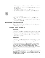
Returning to normal operation

About this task

After performing maintenance on the UPS, follow these steps to put the UPS back
into service and resume normal operation.

Procedure

1.

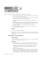
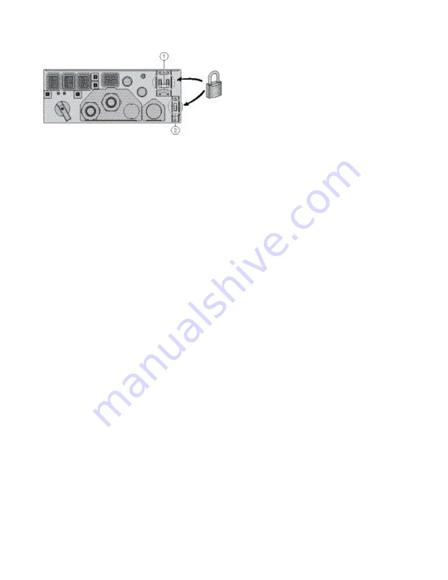
Ensure that the locks are still in place, holding the MBP's UPS Input switch
and UPS Bypass Input switch (3Phase model only) in the

0

(off) position.

Important:

To prevent exposure to hazardous voltage, the switches must

remain in the

0

(off) position during servicing and while the UPS is

disconnected.

2.

Connect the UPS to the MBP.

3.

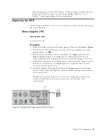
Remove the connection between the exposed wires, insert them through the
terminal cover into the terminal block, and tighten the set screws. Be sure to
connect the UPS AC input cable (blue conduit) and UPS output cable (red
conduit) properly. See “HotSwap MBP connection” on page 30 for details.

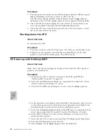
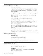
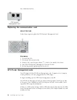
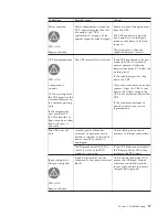
Figure 12. Locking the UPS Input switch and UPS Bypass Input switch (8/11k VA 3Phase)

52

Installation and User's Guide

Содержание RT11.0VA

Страница 1: ...6U Rack or Tower UPS RT8 0kVA and RT11 0VA and Maintenance Bypass Installation and User s Guide ...

Страница 2: ......

Страница 3: ...6U Rack or Tower UPS RT8 0kVA and RT11 0VA and Maintenance Bypass Installation and User s Guide ...

Страница 4: ...he Environmental Notices and User Guide on the Lenovo Documentation CD that came with your product Copyright Lenovo 2015 LIMITED AND RESTRICTED RIGHTS NOTICE If data or software is delivered pursuant a General Services Administration GSA contract use reproduction or disclosure is subject to restrictions set forth in Contract No GS 35F 05925 Lenovo 2015 ...

Страница 5: ... 1Phase units 29 Frequency converter connection 3Phase units 30 HotSwap MBP connection 30 8 11k VA 1Phase 31 8 11k VA 3Phase with common Normal and Bypass AC source 33 8 11k VA 3Phase with separate Normal and Bypass AC source 34 Chapter 5 Operation 37 UPS startup and shutdown 37 Starting the UPS 37 Starting the UPS on Battery 37 Shutting down the UPS 38 UPS start up with HotSwap MBP 38 Monitoring ...

Страница 6: ...ata 70 Creating a personalized support web page 71 Software service and support 71 Hardware service and support 71 Taiwan product service 71 Appendix C Notices 73 Notices 73 Trademarks 74 Important notes 74 Recycling information 75 Particulate contamination 75 Telecommunication regulatory statement 76 Electronic emission notices 76 Appendix D Glossary 81 iv Installation and User s Guide ...

Страница 7: ...rodukt Lees voordat u dit product installeert eerst de veiligheidsvoorschriften Ennen kuin asennat tämän tuotteen lue turvaohjeet kohdasta Safety Information Avant d installer ce produit lisez les consignes de sécurité Vor der Installation dieses Produkts die Sicherheitshinweise lesen Prima di installare questo prodotto leggere le Informazioni sulla Sicurezza Copyright Lenovo 2015 v ...

Страница 8: ...ou identify potential unsafe conditions in a Lenovo product that you are working on Each Lenovo product as it was designed and manufactured has required safety items to protect users and service technicians from injury The information in this section addresses only those items Use good judgment to identify potential unsafe conditions that might be caused by alterations or attachment of non Lenovo ...

Страница 9: ...ith Guidelines for servicing electrical equipment Observe these guidelines when you service electrical equipment v Check the area for electrical hazards such as moist floors nongrounded power extension cords and missing safety grounds v Use only approved tools and test equipment Some hand tools have handles that are covered with a soft material that does not provide insulation from live electrical...

Страница 10: ...ounding of components such as power supplies pumps blowers fans and motor generators do not service these components outside of their normal operating locations v If an electrical accident occurs use caution turn off the power and send another person to get medical aid Safety statements These statements provide the caution and danger information that is used in this documentation Important Each ca...

Страница 11: ...L001 DANGER Hazardous voltage current or energy levels are present inside any component that has this label attached Do not open any cover or barrier that contains this label L001 Safety ix ...

Страница 12: ...roduct to properly wired outlets v When possible use one hand only to connect or disconnect signal cables v Never turn on any equipment when there is evidence of fire water or structural damage v Disconnect the attached power cords telecommunications systems networks and modems before you open the device covers unless instructed otherwise in the installation and configuration procedures v Connect ...

Страница 13: ...ted by local regulations In the United States Lenovo has a process for the collection of this battery For information call 1 800 426 4333 Have the Lenovo part number for the battery unit available when you call C004 C009 CAUTION or or The weight of this part or unit is between 18 and 32 kg 39 7 and 70 5 lb It takes two persons to safely lift this part or unit C009 C011 CAUTION or or The weight of ...

Страница 14: ...22 CAUTION This product might be equipped with a hard wired power cable Ensure that a licensed electrician performs the installation per the national electrical code C022 xii Installation and User s Guide ...

Страница 15: ...ed devices are not to be used as shelves or work spaces Do not place objects on top of rack mounted devices v Each rack cabinet might have more than one power cord Be sure to disconnect all power cords in the rack cabinet when directed to disconnect power during servicing v Connect all devices installed in a rack cabinet to power devices installed in the same rack cabinet Do not plug a power cord ...

Страница 16: ...ed drawers This drawer is a fixed drawer and must not be moved for servicing unless specified by the manufacturer Attempting to move the drawer partially or completely out of the rack might cause the rack to become unstable or cause the drawer to fall out of the rack R001 part 2 of 2 Output power and ampere ratings Important Make sure that the power receptacle is near the equipment and is easily a...

Страница 17: ...uipment and shall be easily accessible v Never install the system near liquids or in an excessively damp environment v Never let a foreign body penetrate inside the system v Never block the ventilation grates of the system v Never expose the system to direct sunlight or source of heat v If the system must be stored prior to installation storage must be in a dry place v The admissible storage tempe...

Страница 18: ...xvi Installation and User s Guide ...

Страница 19: ... License Agreement for Machine Code This document is provided on the Lenovo Documentation CD and it contains the translated license agreement for the product v Warranty Information This multilingual document comes with the device and it contains information about the terms of the warranty Notices and statements The caution and danger statements in this document are also in the multilingual Safety ...

Страница 20: ...mbol Materials Abbreviations Number in the symbols Polyethylene terephthalat PET 01 High density polyethylene HDPE 02 Polyvinyl chloride PVC 03 Low density polyethylene LDPE 04 Polypropylene PP 05 Polystyrene PS 06 Follow all local regulations for the disposal of packing materials Refer to the Lenovo Environmental Notices and User s Guide provided on the documentation CD End of life Lenovo will pr...

Страница 21: ...quency independence and power generator compatibility v Advanced Battery Management ABM technology that uses advanced battery management to increase battery service life optimize recharge time and provide a warning before the end of useful battery life v Selectable High Efficiency mode of operation v Standard communication options one RS 232 communication port one USB communication port and relay ...

Страница 22: ...4 Installation and User s Guide ...

Страница 23: ...27 6 x 17 3 x 5 1 700 x 440 x 130 8kVA Power Module 1 1 42 19 27 6 x 17 3 x 5 1 700 x 440 x 130 11kVA 3 1 Power Module 51 23 27 6 x 17 3 x 5 1 700 x 440 x 130 11kVA Power Module 1 1 46 21 27 6 x 17 3 x 5 1 700 x 440 x 130 8kVA 11kVA Battery Module 143 65 26 8 x 17 3 x 5 1 680 x 440 x 130 Rack installation Copyright Lenovo 2015 5 ...

Страница 24: ...d EBMs are installed in a pre positioned rack Rear panels Figure 1 5594 8KX 5594 8PX RS232 communication port USB communication port Dry relay contacts communication port Connector for Remote On Off ROO control Connectors for automatic recognition of battery module Connector for Remote Power Off RPO control Slot where UPS Network Management Card is installed Connector for battery module power Term...

Страница 25: ... a five button graphical LCD front panel It provides useful information about the UPS itself load status events measurements and settings It also provides a method to change settings The following table shows the indicator status and description Indicator Status Description Green On The UPS is operating normally in Online or in High Efficiency mode Orange On The UPS is in Battery mode Orange On Th...

Страница 26: ...d by the UPS Note If any other indicator displays see Chapter 8 Troubleshooting on page 55 for additional information Operation status Cause Description Is Battery Being Charged Standby mode The UPS output is Off Equipment is not powered until button is pressed Yes Online mode The UPS is operating normally The UPS is powering and protecting the equipment Yes Battery mode 1 beep every 10 seconds A ...

Страница 27: ...from AC input and is not protected by the UPS Yes Display functions Press the Enter button to activate the menu options Use the two middle buttons and to scroll through the menu structure Press the Enter button to select an option Press the button to cancel or return to the previous menu Main menu Submenu Function Measurements Load W VA A pf Input Bypass V Hz Output Efficiency V Hz Battery min V n...

Страница 28: ...MC firmware Com card IPv4 Com card IPv6 Com card MAC Detected accessories Register product Link to Lenovo website User settings The following table displays the options that can be changed by the user Submenu Available settings Default settings Local settings Language language_name Select the desired language from the list Menus status notices and alarms UPS fault Event Log data and settings are i...

Страница 29: ...ge hysteresis from 1 to 10V 10V High Efficiency mode Enabled Disabled Power the output from Bypass for high efficiency Disabled Bypass transfer Transfer if BP AC NOK Enabled Disabled Allow transfer on Bypass out of tolerance Enabled for 8PX and 9PX models Disabled for 8KX and 9KX models Interrupt time If Bypass transfer is enabled Interrupt time 10ms 20ms Define break duration when transfer on Byp...

Страница 30: ...shutdown sequence will not complete and restart will occur immediately Enabled Auto restart Enabled Disabled Authorize the product to restart automatically when utility power recovers after a complete battery discharge Enabled Auto start Enabled Disabled The UPS automatically starts up as soon as utility power is available no need to press the button Disabled Energy saving Disabled 100W 1000W If E...

Страница 31: ...is OFF If Enabled LCD and communication stays ON 90 minutes after UPS is OFF Enabled Remote command Enabled Disabled If Enabled shutdown or restart commands from software are authorized Enabled Bypass standby Enabled Disabled Define if output is powered from Bypass in Standby mode Enabled for 8PX and 9PX models Disabled for 8KX and 9KX models Chapter 2 Presentation 13 ...

Страница 32: ...f battery charge is reached 0 Battery charge mode ABM cycling Constant charge ABM cycling External battery Auto detection Manual EBM set Manual battery set No battery Auto detection Using standard EBM UPS detects automatically the number of EBM connected Deep discharge protection Yes No If set to Yes the UPS automatically prevents battery pack from deep discharge by adapting end of back up time vo...

Страница 33: ...g Dimensions inch mm D x W x H 8 11k VA 1Phase MBP 13 7 6 2 8 7 x 13 2 x 5 1 220 x 336 x 130 8 11k VA 3Phase MBP 12 1 5 5 5 2 x 13 2 x 5 1 132 x 336 x 130 HotSwap MBP controls The HotSwap MBP has a manual rotary switch with two positions v UPS the load is supplied by the UPS and the UPS is supplied by the normal AC power source v Bypass the load is supplied directly by the bypass AC power source T...

Страница 34: ...e following on the UPS display panel v MBP connection to UPS v Bypass switch position Figure 6 8 11k VA 1Phase Input Output terminal blocks Input Output terminal blocks for connection to the UPS Normal AC source switch Signal cable for MBP detection to the UPS Bypass switch 3 30A outlets 30A circuit breaker UPS supply green light Bypass mode red light Figure 7 8 11k VA 3Phase Input Output terminal...

Страница 35: ...entative Unpacking the unit About this task Important Unpacking the unit in a low temperature environment might cause condensation to occur in and on the unit Do not install the unit until the inside and outside of the unit are absolutely dry hazard of electric shock Procedure 1 Unpack the equipment and remove all packing materials and the shipping carton Note Do not lift the UPS or EBM from the f...

Страница 36: ... v Verify that the following additional items are included with the UPS 2 supports for the upright tower position Rail kit for 19 inch enclosures 3 Cable glands for Input Output connection UPS Network Management Card RS232 communication cable USB communication cable Tower stands Documentation and software kit Screwdriver v Verify that the following additional items are included with each EBM 18 In...

Страница 37: ... enclosures Note Disregard the EBM installation instructions if you are installing the EBM with a new UPS at the same time Use the UPS instructions to install both the UPS and the EBM Checking the accessory kit HotSwap MBP Procedure Verify that the following items are included with the MBP Chapter 3 Installation 19 ...

Страница 38: ...n kit for MBP I O covers including screws Rack kit for 19 inch enclosures Fixation kit for Rack mounting including square nuts and screws Tower and wall mounting kit including 2 ears and screws 2 cable glands for UPS Input Bypass connection optional Figure 9 8 11k VA 1Phase Figure 10 8 11k VA 3Phase 20 Installation and User s Guide ...

Страница 39: ... cable s into the battery connector s Up to four EBMs can be connected to the UPS 2 Verify that the EBM connections are tight and that strain relief exists for each cable 3 Connect the battery detection cable s to the connector of the UPS and of the EBM s 4 Check that the battery circuit breaker is switched to the I on position Rack installation Preparing the EBM for rack mounting About this task ...

Страница 40: ...to support the battery packs Set them aside for reinstalling after that the EBM is rack mounted 5 Mount the EBM in the rack 6 Put back the battery packs screw back the metal protection cover and the front panel then clip the center cover Rack mounting of UPS EBM and accessory modules Procedure Follow steps 1 to 4 in Preparing the EBM for rack mounting on page 21 for module mounting on the rails 22...

Страница 41: ...task To install the unit in a tower configuration Procedure 1 Place the UPS on a flat stable surface in its final location 2 Always keep 150 mm of free space behind the UPS rear panel 3 If installing additional units place them next to the UPS in their final location Chapter 3 Installation 23 ...

Страница 42: ...le of vision of the LCD panel as shown Installing the communication card About this task Follow these steps to install the UPS Network Management Card if it is not preinstalled Note It is not necessary to shut down the UPS before installing the card 24 Installation and User s Guide ...

Страница 43: ...0A D curve 50A 5594 9KX 11k VA 1Phase D curve 63 70A D curve 63 70A D curve 63 70A 2 RISK OF VOLTAGE BACKFEED The system has its own power source the battery Isolate the UPS and check for hazardous voltage upstream and downstream during lockout tagout operation Terminal blocks might be energized even if the system is disconnected from the AC power source 3 Although the UPS does not contain anti ba...

Страница 44: ...inimum wire size Tightening torque All 4 25 mm2 12 4 AWG 10 mm2 8 AWG 105 C 16 mm2 6 AWG 90 C 2 03 Nm 18 in lb Copper wire solid or stranded Installation depending on the system earthing arrangement SEA UPS with common Normal and Bypass AC inputs 26 Installation and User s Guide ...

Страница 45: ... the upstream protection devices Normal AC source and Bypass AC source are open O off Always connect the ground wire first Important Before connecting the HotSwap MBP to the UPS make sure the UPS has been properly shut down Always connect the ground wire first Access to terminal blocks Procedure 1 Remove the terminal blocks cover one screw 2 Punch the knockouts and insert the cables conduits insid...

Страница 46: ... back and secure the terminal blocks cover with the screw 7 Tighten the cable glands Common input sources connection 3Phase units About this task 1 Make sure the jumper is connected 2 Insert the Normal AC cable through the cable gland 3 Connect the five cables to the Normal AC source terminal blocks 4 Insert the Output cable through the cable gland 5 Connect the three cables to the Output terminal...

Страница 47: ...this task 1 Remove the jumper 2 Insert the Normal AC cable through the cable gland 3 Connect the five cables to the Normal AC source terminal blocks 4 Insert the Bypass AC cable through the cable gland 5 Connect the three cables to the Bypass AC source terminal blocks 6 Insert the Output cable through the cable gland 7 Connect the three cables to the Output terminal blocks 8 Put back and secure th...

Страница 48: ...fied electrical personnel Before carrying out any connection check that the upstream protection devices Normal AC source and Bypass AC source are open O off Always connect the ground wire first 1 Remove the jumper 2 Insert the Normal AC cable through the cable gland 3 Connect the five cables for 8PX and 9PX models or three cables for KX models to the Normal AC source terminal blocks Do not connect...

Страница 49: ...e 3 wires of this blue color conduit to the TO UPS NORMAL AC SOURCE MBP terminal blocks 5 Insert the provided conduit with red color coding through the FROM UPS OUTPUT conduit fitting Note Take care to leave the conduit end with red label on opposite side for connection to UPS 6 Connect the 3 wires of this red color conduit to the FROM UPS OUTPUT MBP terminal blocks 7 Put back the MBP I O UPS conn...

Страница 50: ...connections 13 Connect the MBP detection cable to the specific UPS connector 14 Put back and secure the I O terminal blocks cover of the UPS 15 Remove the top cover of the MBP I O cover after removing the 3 screws 16 Punch the knockouts of MBP I O cover and insert cable glands of UPS or conduit fittings inside 17 Insert the Normal AC source cable through the cable gland or a conduit through the co...

Страница 51: ...and Bypass AC source Procedure 1 Connect the two integrated power cables to the UPS I O terminal blocks following color coding on the cables and the UPS I O cover blue for UPS Input red for UPS Output Chapter 4 Power cables connection 33 ...

Страница 52: ...r and the UPS Input Bypass jumper inside the UPS I O cover 6 Insert the Output cable through the cable gland 7 Connect the wires to the Output terminal blocks 8 Tighten the cable glands 9 Slide back and secure the MBP I O cover with the 5 screws 8 11k VA 3Phase with separate Normal and Bypass AC source Procedure 1 Slide the MBP Bypass Input cover after removing the 3 screws 2 Punch the UPS Bypass ...

Страница 53: ...pass Input cover with the 3 screws 7 Connect the two integrated power cables and the previously installed Bypass Input power cable to the UPS I O terminal blocks following color coding on the cables and the UPS I O cover blue for UPS Input red for UPS Output yellow for UPS Input Bypass Remove the Input Bypass AC jumper on UPS 8 Connect the MBP detection cable to the specific UPS connector 9 Slide ...

Страница 54: ... the wires to the Normal AC source Input terminal blocks 14 Insert the Bypass AC source cable through the cable gland 15 Connect the wires to the Bypass AC source Input BP terminal blocks 16 Insert the Output cable through the cable gland 17 Connect the wires to the Output terminal blocks 18 Tighten the cable glands 19 Slide back and secure the MBP I O cover with the 5 screws 36 Installation and U...

Страница 55: ...nel display changes status to UPS starting 6 Check the UPS front panel display for active alarms or notices Resolve any active alarms before continuing See the Troubleshooting section If the indicator is on do not proceed until all alarms are clear Check the UPS status from the front panel to view the active alarms Correct the alarms and restart if necessary 7 Verify that the indicator illuminates...

Страница 56: ...ify that the total equipment ratings do not exceed the UPS capacity to prevent an overload alarm Procedure 1 Check that the UPS is correctly connected to the HotSwap MBP see HotSwap MBP connection on page 30 2 Verify that the MBP terminal blocks are connected to the normal AC source and if so wired to the Bypass AC source 3 Check that the MBP s manual Bypass switch is set to the Bypass position 4 ...

Страница 57: ...ur equipment High Efficiency and Energy Saving settings take the UPS out of online mode to minimize heat contribution to the rack environment but reduce the protection of your equipment See User settings on page 10 Battery mode When the UPS is operating without utility power the alarm beeps once every ten seconds and the indicator illuminates solid The necessary energy is provided by the battery p...

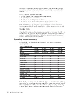
Страница 58: ...ry and the communication ports are powered Operating modes summary The following table summarizes the characteristics of your UPS unit in each operating mode Table 3 Operating modes Mode Online Battery Bypass Standby Load powered powered powered no power Batteries charging discharging charging charging Protection features Power failure yes n a no no Power sag yes n a no no Power surge yes n a no n...

Страница 59: ...Control Go to Bypass 2 Then press Escape and select Settings In Out settings High Efficiency mode 3 Select Enabled and Enter to confirm The UPS goes into Bypass mode and transfers to Battery mode in the event utility power fails Configuring Bypass settings The following settings are available for configuring Bypass operation for special situations Normally these settings will not need to be change...

Страница 60: ...y capacity goes below 20 This threshold can be modified using the LCD panel External battery setting The number of Extended Battery Modules EBMs is automatically detected or it can be set manually using the LCD panel see External battery in User settings on page 10 Deep discharge protection This setting is recommended to avoid damaging the battery packs The warranty is void if deep discharge prote...

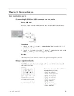
Страница 61: ...nication port on the UPS Results The UPS can now communicate with Lenovo power management software Relay output contacts The UPS incorporates four relay outputs each one is available with a normally closed or open contact n o contact normally open n c contact normally closed Status active information if contact between pin and common is closed v Pin 1 not on Bypass v Pin 2 load not protected v Pin...

Страница 62: ... the room temperature is too high When RPO is activated the UPS disables the output and all its power converters immediately The UPS remains on to alarm the fault Important The RPO circuit is an IEC 60950 safety extra low voltage SELV circuit This circuit must be separated from any hazardous voltage circuits Note Important notes v The RPO must not be connected to any utility connected circuits The...

Страница 63: ...o the back of the UPS and fix the screws 5 Connect and restart the UPS 6 Open the external remote shut down contact to test the function Note Always test the RPO function before applying your critical load to avoid accidental load loss Connectivity card The UPS Network Management Card allows the UPS to communicate in Ethernet environments The card has SNMP and HTTP capabilities as well as monitori...

Страница 64: ... The UPS ships with the UPS Power Management suite It operates on a computer running Windows or Linux plugged into the UPS output To begin installing see the UPS Power Management suite CD The UPS Power Management suite provides real time graphics of UPS power data It also gives you a complete record of critical power events and it notifies you of important UPS or power information If there is a ut...

Страница 65: ...nths by connecting the UPS to utility power The EBM will charge to 90 capacity in less than 3 hours However the battery packs should be allowed to charge for 48 hours after long term storage Check the battery recharge date on the shipping carton label If the date has passed and the battery packs were never recharged do not use them Contact your service representative Replacing battery packs When t...

Страница 66: ... of battery packs is required Refer to your local codes for disposal requirements v Never dispose of batteries in a fire Batteries might explode when exposed to flame v Do not open or mutilate batteries Released electrolyte is harmful to the skin and eyes and can be extremely toxic v Determine if the battery pack is inadvertently grounded If inadvertently grounded remove source from ground Contact...

Страница 67: ...to support the battery pack See Recycling the used equipment on page 53 for proper disposal 5 Verify that the replacement batteries have the same rating as the batteries being replaced 6 Slide the new battery pack into the UPS Push the battery pack firmly to ensure a proper connection 7 Screw the metal protective cover back onto the unit 8 Reinstall the front bezel by tightening the four captive s...

Страница 68: ...and will not harm personnel Insert the EBM cable into the battery connector quickly and firmly 3 Plug the EBM cable s into the battery connector s Up to four EBMs can be connected to the UPS 4 Verify that the EBM connections are tight and that adequate strain relief exists for each cable 5 Connect the battery detection cable s to the connector of the UPS and of the EBM s Testing a new battery pack...

Страница 69: ...itch on the MBP to the Bypass position The Bypass mode red light on the MBP goes on indicating that the load is powered directly from utility power or if so wired by the Bypass AC source 4 Pull out the yellow tab on the MBP rotary switch and install a lock to ensure that the switch remains in the Bypass position to prevent the load from losing power during servicing 5 Switch the MBP s UPS Input sw...

Страница 70: ...s switch is locked Do not manipulate the switch unless the UPS is connected to the MBP Returning to normal operation About this task After performing maintenance on the UPS follow these steps to put the UPS back into service and resume normal operation Procedure 1 Ensure that the locks are still in place holding the MBP s UPS Input switch and UPS Bypass Input switch 3Phase model only in the 0 off ...

Страница 71: ... MBP Do not continue to the next step if the UPS mode green light on the MBP is off If the green light is off and the manual rotary switch is moved to the UPS position the load will lose power 10 Remove the lock and set the MBP s manual Bypass switch to the UPS position The Bypass mode red light on the MBP goes off indicating that the load is now powered by the UPS 11 On the UPS select Control Go ...

Страница 72: ...y as required by local ordinances or regulations Do not discard waste electrical or electronic equipment WEEE in the trash For proper disposal contact your local recycling reuse or hazardous waste center Do not discard the UPS or the UPS batteries in the trash This product contains sealed lead acid batteries and must be disposed of properly For more information contact your local recycling reuse o...

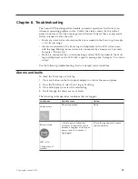
Страница 73: ...ed LED recorded in the Fault log and displayed on the LCD with a specific message box Example Out short circuit Use the following troubleshooting chart to interpret alarm conditions Alarms and faults To check the Event log or Fault log 1 Press any button on the front panel display to activate the menu options 2 Press the button to select Event log or Fault log 3 Press Enter to review the selected ...

Страница 74: ...The battery test is failed because of a bad battery pack because the battery pack is not connected battery pack or because the battery minimum voltage is reached in Advanced Battery Management ABM cycling mode Verify that all battery packs are properly connected Start a new battery test if the condition persists contact your service representative The UPS does not provide the expected backup time ...

Страница 75: ...n when the temperature drops 5 C below the warning level If the condition persists shut down the UPS Clear vents and remove any heat sources Allow the UPS to cool Ensure the airflow around the UPS is not restricted Restart the UPS If the condition continues to persist contact your service representative The UPS does not start A utility power failure has occurred an upstream circuit breaker is trip...

Страница 76: ...ion ready when you call for service v Equipment type and model number v Serial number v Firmware version number v Date of failure or problem v Symptoms of failure or problem v Customer address and contact information If repair is required you will be given a Returned Material Authorization RMA number This number must appear on the outside of the package and on the Bill Of Lading if applicable Use ...

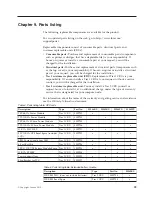
Страница 77: ...e unit You may install a Tier 2 CRU yourself or request Lenovo to install it at no additional charge under the type of warranty service that is designated for your compute node For information about the terms of the warranty and getting service and assistance see the Warranty Information document Table 4 Parts listing table UPS units Description Type Part No 55948KX 55949KX 55948PX 55949PX 9PX 8KV...

Страница 78: ...ype Part No 55949BX EBM Power Cord 6 Feet 240V Tier 1 CRU 00FP795 x 4 Post Rail Kit Tier 2 CRU 00FP796 x 9PX 8 11K UPS Battery Module Spare Tier 2 CRU 00FP798 x Tower pedestal feet Tier 1 CRU 00FP825 x Ship Bracket for 9PX Tier 1 CRU 00FP827 x 60 Installation and User s Guide ...

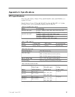
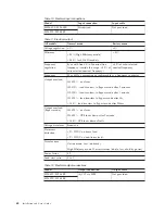
Страница 79: ...0V 240V output Table 7 EBM model list Model Configuration EBM voltage For power ratings 5594 9BX Rack Tower 240Vdc 8000 11000VA Table 8 Electrical input Nominal frequency 50 60Hz auto sensing Frequency range 50Hz 40 60Hz before transfer to battery 60Hz 50 70Hz before transfer to battery Bypass voltage range 20 15 of nominal value default Noise filtering MOV for normal and common mode noise Table 9...

Страница 80: ...0 102 no alarm 102 110 load transfers to Bypass mode after 2 minutes 110 125 load transfers to Bypass mode after 1 minute 125 150 load transfers to Bypass mode after 10s 150 load transfers to Bypass mode after 900ms Output overload Bypass mode 100 125 no alarm 125 150 UPS shuts down after 1 minute 150 UPS shuts down after 1s Voltage waveform Sinewave Harmonic distortion 2 THDV on linear load 5 THD...

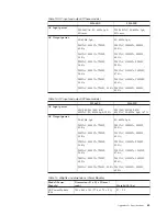
Страница 81: ...C input and output 3Phase models 5594 8PX 5594 9PX AC Input power 350 360 380 400 415 430VAC 50 60Hz 3ph 13 3A 350 360 380 400 415 430VAC 50 60Hz 3ph 16 7A AC Output power 50 60Hz 1ph 200VAC 8000VA 7200W 40 0A 208VAC 8000VA 7200W 38 5A 220VAC 8000VA 7200W 36 4A 230VAC 8000VA 7200W 34 8A 240VAC 8000VA 7200W 33 3A 250VAC 8000VA 7200W 32 0A 50 60Hz 1ph 200VAC 10000VA 9000W 50 0A 208VAC 10000VA 9000W ...

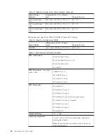
Страница 82: ...43 65 Table 17 Environmental and safety standards EMC certifications IEC EN 62040 1 2008 IEC EN 62040 2 2006 Cat C2 IEC EN 62040 3 2011 IEC 60950 1 EMC Emissions for output cable 10m CISPR22 Class A AS NZS 22 Class A IEC 61000 3 2 3 12 IEC 61000 3 3 3 11 EMC Immunity IEC 61000 2 2 IEC 61000 4 2 Level 3 IEC 61000 4 3 Level 3 IEC 61000 4 4 Level 4 also on signal ports IEC 61000 4 5 Level 4 Criteria ...

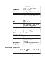
Страница 83: ... float service life at 25 C 77 F Lifetime is reduced above 30 C 86 F Monitoring Advanced monitoring for earlier failure detection and warning Battery port External three pole SBS75G White connector on Power Module for connecting to EBM EBM battery cable length 40cm 15 7in Table 19 Communication options Communication bay 1 available independent communication bay for connectivity cards Compatible co...

Страница 84: ... 2 2006 FCC part 15 Class A IEC 62040 2 Ed 2 2005 EN 62040 2 Ed 2 2006 Performance IEC EN 62040 3 Ed 2 0 2011 ESD IEC 61000 4 2 level 3 Radiated field IEC 61000 4 3 level 3 EFT IEC 61000 4 4 level 4 Fast transients IEC 61000 4 5 level 4 Electromagnetic field IEC 61000 4 6 level 3 Conducted magnetic field IEC 61000 4 8 level 4 Marking cULus Listed CE CE Environment Operating temperature 0 to 40 C 3...

Страница 85: ...m source UPS power rating Upstream circuit breaker 8000VA D curve 50A 11000VA D curve 70A Recommended upstream protection bypass AC source UPS power rating Upstream circuit breaker 8000VA D curve 50A 11000VA D curve 70A Appendix A Specifications 67 ...

Страница 86: ...68 Installation and User s Guide ...

Страница 87: ...e firmware and operating system device drivers for your Lenovo product The Lenovo Warranty terms and conditions state that you the owner of the Lenovo product are responsible for maintaining and updating all software and firmware for the product unless it is covered by an additional maintenance contract Your service technician will request that you upgrade your software and firmware if the problem...

Страница 88: ...or using the diagnostic programs The troubleshooting information or the diagnostic programs might tell you that you need additional or updated device drivers or other software Lenovo maintains pages on the World Wide Web where you can get the latest technical information and download device drivers and updates To access these pages go to http www ibm com supportportal Getting help and information ...

Страница 89: ...ort Line and other IBM services see http www ibm com services or see http www ibm com planetwide for support telephone numbers In the U S and Canada call 1 800 IBM SERV 1 800 426 7378 Hardware service and support IBM is Lenovo s preferred service provider for the System x Flex System and NeXtScale System products You can receive hardware service through your Lenovo reseller or from IBM To locate a...

Страница 90: ...IBM Taiwan Corporation 3F No 7 Song Ren Rd Taipei Taiwan Telephone 0800 016 888 72 Installation and User s Guide ...

Страница 91: ...es in certain transactions therefore this statement may not apply to you This information could include technical inaccuracies or typographical errors Changes are periodically made to the information herein these changes will be incorporated in new editions of the publication Lenovo may make improvements and or changes in the product s and or the program s described in this publication at any time...

Страница 92: ... variable read rate Actual speeds vary and are often less than the possible maximum When referring to processor storage real and virtual storage or channel volume KB stands for 1 024 bytes MB stands for 1 048 576 bytes and GB stands for 1 073 741 824 bytes When referring to hard disk drive capacity or communications volume MB stands for 1 000 000 bytes and GB stands for 1 000 000 000 bytes Total u...

Страница 93: ...iewed or used as definitive limits because numerous other factors such as temperature or moisture content of the air can influence the impact of particulates or environmental corrosives and gaseous contaminant transfer In the absence of specific limits that are set forth in this document you must implement practices that maintain particulate and gas levels that are consistent with the protection o...

Страница 94: ...rsuant to Part 15 of the FCC Rules These limits are designed to provide reasonable protection against harmful interference when the equipment is operated in a commercial environment This equipment generates uses and can radiate radio frequency energy and if not installed and used in accordance with the instruction manual may cause harmful interference to radio communications Operation of this equi...

Страница 95: ...t Dieses Produkt entspricht den Schutzanforderungen der EU Richtlinie 2004 108 EG früher 89 336 EWG zur Angleichung der Rechtsvorschriften über die elektromagnetische Verträglichkeit in den EU Mitgliedsstaaten und hält die Grenzwerte der EN 55022 Klasse A ein Um dieses sicherzustellen sind die Geräte wie in den Handbüchern beschrieben zu installieren und zu betreiben Des Weiteren dürfen auch nur v...

Страница 96: ...verfahren ist nach Paragraph 9 EMVG in Verbindung mit der entsprechenden Kostenverordnung Amtsblatt 14 93 kostenpflichtig Anmerkung Um die Einhaltung des EMVG sicherzustellen sind die Geräte wie in den Handbüchern angegeben zu installieren und zu betreiben Japan VCCI Class A statement This is a Class A product based on the standard of the Voluntary Control Council for Interference VCCI If this equ...

Страница 97: ...uipment for business Type A Sellers and users need to pay attention to it This is for any areas other than home Russia Electromagnetic Interference EMI Class A statement People s Republic of China Class A electronic emission statement Taiwan Class A compliance statement Appendix C Notices 79 ...

Страница 98: ...80 Installation and User s Guide ...

Страница 99: ...which the load is supplied directly by the Bypass AC source if it is within the tolerances defined by the user This mode eliminates the double conversion which reduces the consumption of electrical power but introduces a switching delay Load Devices or equipment connected to the UPS output Low battery warning A battery level indicating that battery power is low and that action should be taken to p...

Страница 100: ...82 Installation and User s Guide ...

Страница 101: ......

Страница 102: ...Part Number 00WA361 Printed in USA 1P P N 00WA361 ...

Отзывы: