background image

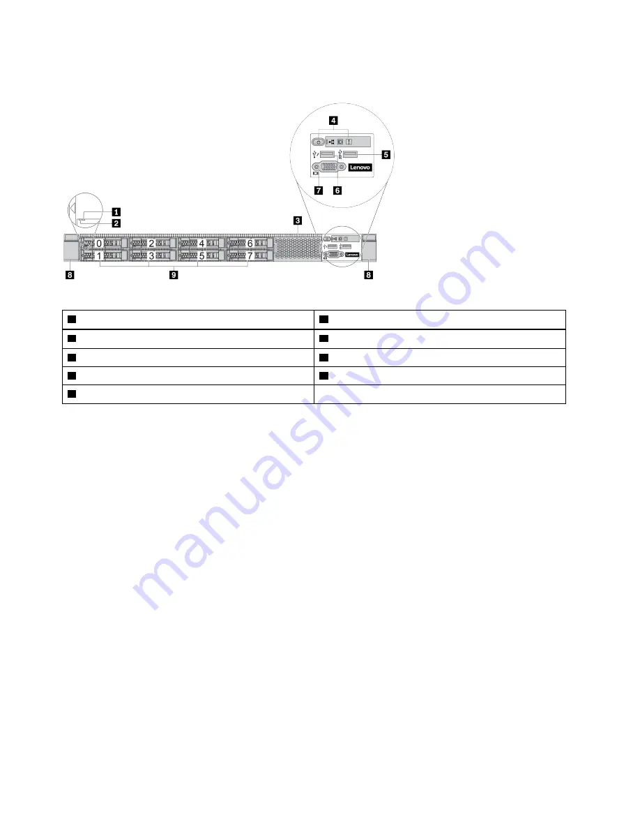
Server model with eight 2.5-inch drive bays

Table 2.  Components on the front of the server

Drive status LED

Drive activity LED

Drive bay filler

Diagnostics panel

USB 3.0 connector

USB 2.0 connector

VGA connector

Rack latch

Drive bays

Note:

For more information about each component, see “Front components overview” on page 9.

6

HR630X V2 User Guide

Содержание HR630X V2

Страница 1: ...HR630X V2 User Guide Machine Types 7D4C ...

Страница 2: ...n addition be sure that you are familiar with the terms and conditions of the Lenovo warranty for your server which can be found at http datacentersupport lenovo com warrantylookup First Edition June 2021 Copyright Lenovo 2021 LIMITED AND RESTRICTED RIGHTS NOTICE If data or software is delivered pursuant to a General Services Administration GSA contract use reproduction or disclosure is subject to...

Страница 3: ...wap power supply unit 54 Install a hot swap power supply unit 55 Memory module replacement 57 Remove a memory module 57 Memory module installation rules 58 Install a memory module 59 M 2 adapter and M 2 drive replacement 61 Remove the M 2 adapter and M 2 drive 62 Adjust the retainer on the M 2 adapter 64 Install the M 2 adapter and M 2 drive 65 OCP 3 0 Ethernet adapter replacement 67 Remove the OC...

Страница 4: ...te the parts replacement 110 Chapter 5 Problem determination 113 Appendix A Getting help and technical assistance 115 Before you call 115 Collecting service data 116 Appendix B Notices 117 Trademarks 118 Particulate contamination 118 Telecommunication regulatory statement 118 Electronic emission notices 119 Index 121 ii HR630X V2 User Guide ...

Страница 5: ...es voordat u dit product installeert eerst de veiligheidsvoorschriften Ennen kuin asennat tämän tuotteen lue turvaohjeet kohdasta Safety Information Avant d installer ce produit lisez les consignes de sécurité Vor der Installation dieses Produkts die Sicherheitshinweise lesen Prima di installare questo prodotto leggere le Informazioni sulla Sicurezza Les sikkerhetsinformasjonen Safety Information ...

Страница 6: ...e Workplace Regulations CAUTION This equipment must be installed or serviced by trained personnel as defined by the NEC IEC 62368 1 IEC 60950 1 the standard for Safety of Electronic Equipment within the Field of Audio Video Information Technology and Communication Technology Lenovo assumes you are qualified in the servicing of equipment and trained in recognizing hazards energy levels in products ...

Страница 7: ...ious unsafe conditions such as metal filings contamination water or other liquid or signs of fire or smoke damage 5 Check for worn frayed or pinched cables 6 Make sure that the power supply cover fasteners screws or rivets have not been removed or tampered with Security advisories Lenovo is committed to developing products and services that adhere to the highest security standards in order to prot...

Страница 8: ......

Страница 9: ...escription Dimension Dimension without package 813 mm x 482 mm x 43 mm 32 x 19 x 2 Dimension with package 998 mm x 587 mm x 224 mm 39 x 23 x 9 Package weight 25 kg 55 lb Processor Support up to two Intel Ice Lake processors Support SKT P LGA 4189 architecture Support 3 UPI links up to 11 2 GT s Thermal Design Power TDP up to 270 watts Heat sink Standard heat sink High performance heat sink T shape...

Страница 10: ...NVMe hot swap drives 4 x EDSFF hot swap drives Rear drive bays 2 x 2 5 NVMe hot swap drives Expansion slots Depending on the model your server supports up to three PCIe slots in the rear Your server supports the following types of PCIe slots PCIe x16 LP PCIe x16 x16 16 LP LP LP PCIe x16 x16 LP FHHL Your server supports up to one slot for OCP 3 0 Ethernet adapter For locations of the PCIe and OCP s...

Страница 11: ...an 4056 24000 RPM Electrical input AC input Platinum 100 240 VDC 500 W 750 W 1100 W Titanium 200 240 VDC 750 W DC input 240 HVDC 500 W 750 W 1100 W Chinese Mainland ONLY CAUTION Use Lenovo Capacity Planner to calculate the required power capacity for what is configured for your server More information about Lenovo Capacity Planner is available at Lenovo Capacity Planner website Ensure that the pow...

Страница 12: ...d data center environment and recommended to be placed in industrial data center Air temperature Operating ASHRAE class A2 10 35 C 50 95 F when the altitude exceeds 900 m 2953 ft the maximum ambient temperature value decreases by 1 C 1 8 F with every 300 m 984 ft of altitude increase ASHRAE class A3 5 40 C 41 104 F when the altitude exceeds 900 m 2953 ft the maximum ambient temperature value decre...

Страница 13: ...ries by model Depending on the model your server might look slightly different from the illustrations in this topic Refer to the following front view for different server models Server models with eight 2 5 inch front drive bays on page 6 Server models with ten 2 5 inch front drive bays on page 7 Server model with four 3 5 inch and or EDSFF drive bays on page 8 Copyright Lenovo 2021 5 ...

Страница 14: ...the server 1 Drive status LED 2 Drive activity LED 3 Drive bay filler 4 Diagnostics panel 5 USB 3 0 connector 6 USB 2 0 connector 7 VGA connector 8 Rack latch 9 Drive bays Note For more information about each component see Front components overview on page 9 6 HR630X V2 User Guide ...

Страница 15: ...t of the server 1 Drive status LED 2 Drive activity LED 3 Diagnostics panel 4 USB 3 0 connector 5 USB 2 0 connector 6 VGA connector 7 Rack latch 8 Drive bays Note For more information about each component see Front components overview on page 9 Chapter 2 Server components 7 ...

Страница 16: ...the server 1 Rack latch 2 EDSFF drive bays 3 VGA connector 4 USB 2 0 connectors 5 USB 3 0 connectors 6 Diagnostics panel 7 3 5 inch drive bays 8 Drive status LED 9 Drive activity LED Note For more information about each component see Front components overview on page 9 8 HR630X V2 User Guide ...

Страница 17: ...sh per second Green The server is off and is ready to be powered on standby state Fast blinking about four flashes per second Green The server is off but the BMC is initializing and the server is not ready to be powered on Off None There is no ac power applied to the server 2 Network activity LED Compatibility of the NIC adapter and the network activity LED NIC adapater Network activity LED OCP 3 ...

Страница 18: ...to be running at low speed A hot swap fan has been removed The power supply has a critical error The power supply is not connected to the power Check the event log to determine the exact cause of the error Alternatively follow the light path diagnostics to determine if additional LEDs are lit that will direct you to identify the cause of the error Off None The server is off or the server is on and...

Страница 19: ...s Rack latches If your server is installed in a rack you can use the rack latches to help you slide the server out of the rack You also can use the rack latches and screws to secure the server in the rack so that the server cannot slide out especially in vibration prone areas For more information refer to the Rack Installation Guide that comes with your rail kit USB 2 0 3 0 connectors The USB 2 0 ...

Страница 20: ...y different from the illustrations in this topic Refer to the following rear view for different server models Server model with three PCIe slots on page 13 Server model with two PCIe slots on page 14 Server model with two hot swap 2 5 inch rear drive bays and one PCIe slot on page 15 12 HR630X V2 User Guide ...

Страница 21: ...the illustration below Table 5 Components on the rear of the server 1 Ethernet connectors on OCP 3 0 Ethernet adapter 2 Network management interface 3 USB 3 0 connector 4 VGA connector 5 NMI button 6 Power supply 1 7 Power supply 0 8 PCIe slot 3 9 PCIe slot 2 10 PCIe slot 1 Note For more information about each component see Rear components overview on page 16 Chapter 2 Server components 13 ...

Страница 22: ...the illustration below Table 6 Components on the rear of the server 1 Ethernet connectors on OCP 3 0 Ethernet adapter 2 Network management interface 3 USB 3 0 connector 4 VGA connector 5 NMI button 6 Power supply 1 7 Power supply 0 8 Rear wall bracket 9 PCIe slot 2 10 PCIe slot 1 Note For more information about each component see Rear components overview on page 16 14 HR630X V2 User Guide ...

Страница 23: ...might look slightly different from the illustration below Table 7 Components on the rear of the server 1 Ethernet connectors on OCP 3 0 Ethernet adapter 2 Network management interface 3 USB 3 0 connector 4 VGA connector 5 NMI button 6 Power supply 1 7 Power supply 0 8 Rear 2 5 inch drive bays 9 PCIe slot 1 Note For more information about each component see Rear components overview on page 16 Chapt...

Страница 24: ...The OCP 3 0 Ethernet adapter provides two or four extra Ethernet connectors for network connections One of the Ethernet connectors on the OCP 3 0 Ethernet adapter can also function as a management connector using the shared management capacity Hot swap drives and drive bays The drive bays on the front and rear of your server are designed for hot swap drives The number of the installed drives in yo...

Страница 25: ...EDs near the power cord connector For information about the LEDs see Rear view LEDs on page 18 USB 3 0 connectors The USB 3 0 connectors can be used to attach a USB compatible device such as a USB keyboard USB mouse or USB storage device VGA connector The VGA connectors on the front and rear of the server can be used to attach a high performance monitor a direct drive monitor or other devices that...

Страница 26: ...iew of the server 1 Ethernet link LED 2 Ethernet activity LED 3 Power input LED 4 Power output LED 5 Power supply error LED 6 System ID LED with button 1 Ethernet link LED 2 Ethernet activity LED The BMC network connector has two status LEDs Ethernet status LED Color Status Description 1 Ethernet link LED Green On Network link is established None Off Network link is disconnected 2 Ethernet activit...

Страница 27: ...t the Setup utility go to Advanced Power Zero Output and select Disable If you disable the zero out mode both power supplies will be in the active state Off The server is powered off or the power supply is not working properly If the server is powered on but the LED is off replace the power supply 5 Power supply error LED Yellow The power supply has failed To resolve the issue replace the power su...

Страница 28: ...d Connector 10 TPM Module Connector 11 VROC Key Connector 12 Front Panel USB Connector 13 3V Battery BR2032 14 DIMM 1 32 Error LEDs 15 Front VGA Connector 16 Front Panel Connector 17 MCIO 0 Connector 18 MCIO 1 Connector 19 Fan Board Connector 20 System Board Lift Handle 21 Fan Board Power Connector 22 MCIO 4 Connector 23 MCIO 5 Connector 24 EDSFF Power Connector 25 PSU 1 Connector 26 MCIO 3 Connec...

Страница 29: ...th no service agreement you will be charged for the installation Tier 2 customer replaceable unit CRU You may install a Tier 2 CRU yourself or request Lenovo to install it at no additional charge under the type of warranty service that is designated for your server Field replaceable unit FRU FRUs must be installed only by trained service technicians Consumable and Structural parts Purchase and rep...

Страница 30: ...2 CRU FRU Consumable and Structural parts 1 Top cover 2 Standard air baffle 3 Riser assembly LP 4 Riser assembly LP LP 5 Riser assembly LP FH 6 Rearwall bracket 7 PCIe adapter 8 System board 9 RAID super capacitor holder on chassis 22 HR630X V2 User Guide ...

Страница 31: ... bay filler 18 2 x 2 2 5 inch drive bay filler 19 2 x 3 2 5 inch drive bay filler 20 2 5 inch drive 21 3 5 inch drive 22 8 x 2 5 inch front drive backplane 23 10 x 2 5 inch front drive backplane 24 4 x 3 5 inch front drive backplane 25 2 x 2 5 inch rear drive cage 26 2 x 2 5 inch rear drive backplane 27 Fan module 28 Memory module 29 Chassis 30 EDSFF 31 Standard heat sink 32 Performance heat sink ...

Страница 32: ...24 HR630X V2 User Guide ...

Страница 33: ...ate the connectors 5 Power on the server See Power on the server on page 25 6 Validate that the server hardware was set up successfully Make sure that all LEDs are in normal states 7 Configure the system Power on the server After the server performs a short self test power status LED flashes quickly when connected to input power it enters a standby state power status LED flashes once per second Th...

Страница 34: ...r more than 4 seconds to force a shutdown When in a standby state the server can respond to remote power on requests sent to the BMC For information about powering on the server see Power on the server on page 25 26 HR630X V2 User Guide ...

Страница 35: ...s part of a cluster solution verify that the latest level of code is supported for the cluster solution before you update the code It is good practice to make sure that the server is working correctly before you install an optional component Keep the working area clean and place removed components on a flat and smooth surface that does not shake or tilt Do not attempt to lift an object that might ...

Страница 36: ...30 seconds after removal A removed hot swap drive must be replaced within two minutes after removal A removed hot swap power supply must be replaced within two minutes after removal Every air baffle that comes with the server must be installed when the server starts some servers might come with more than one air baffle Operating the server with a missing air baffle might damage the processor All p...

Страница 37: ...n to remove the air baffle About this task Depending on the model your server might not have an air baffle installed The air baffle you want to remove might be different from the following illustrations but the removal method is the same S033 CAUTION Hazardous energy present Voltages with hazardous energy might cause heating when shorted with metal which might result in spattered metal burns or bo...

Страница 38: ... Install the air baffle on page 30 Install the air baffle Use this information to install the air baffle About this task Depending on the model your server might not have an air baffle installed The air baffle you want to install might be different from the following illustrations but the removal method is the same S033 CAUTION Hazardous energy present Voltages with hazardous energy might cause he...

Страница 39: ...e according to indications on it Figure 6 Air baffle installation Step 2 Lower the air baffle into the chassis and press the air baffle down until it is securely seated After you finish 1 Complete the parts replacement See Complete the parts replacement on page 110 CMOS battery replacement Use this information to remove and install the CMOS battery Remove the CMOS battery Use this information to r...

Страница 40: ...r you replace the CMOS battery you must reconfigure the server and reset the system date and time S004 CAUTION When replacing the lithium battery use only Lenovo specified part number or an equivalent type battery recommended by the manufacturer If your system has a module containing a lithium battery replace it only with the same module type made by the same manufacturer The battery contains lith...

Страница 41: ...attery as local ordinances or regulations required Install the CMOS battery Use this information to install the CMOS battery About this task The following tips describe information that you must consider when installing the CMOS battery Lenovo has designed this product with your safety in mind The lithium battery must be handled correctly to avoid possible danger If you install the CMOS battery yo...

Страница 42: ...rn off the electrical current supplied to the device The device also might have more than one power cord To remove all electrical current from the device ensure that all power cords are disconnected from the power source Attention Read Installation Guidelines on page 27 to ensure that you work safely Power off the server and disconnect all power cords for this task Prevent exposure to static elect...

Страница 43: ...s panel You can remove other front I O assemblies in the same way Attention Read Installation Guidelines on page 27 to ensure that you work safely Power off the server and disconnect all power cords for this task Prevent exposure to static electricity which might lead to system halt and loss of data by keeping static sensitive components in their static protective packages until installation and h...

Страница 44: ...front I O assemblies in the same way Attention Read Installation Guidelines on page 27 to ensure that you work safely Power off the server and disconnect all power cords for this task Prevent exposure to static electricity which might lead to system halt and loss of data by keeping static sensitive components in their static protective packages until installation and handling these devices with an...

Страница 45: ...ctions in addition to the instructions in this topic The electromagnetic interference EMI integrity and cooling of the server are protected by having all drive bays covered or occupied The vacant bays are either covered by an EMI protective panel or occupied by drive fillers When installing a drive save the removed drive filler in case that you later remove the drive and need the drive filler to c...

Страница 46: ...t operate the server for more than two minutes without either a drive or a drive filler installed in each bay Procedure Step 1 Slide the release latch to the left to open the drive tray handle Figure 11 Opening the drive tray handle Step 2 Grasp the handle and slide the drive out of the drive bay Figure 12 Hot swap drive removal After you finish 1 Install the drive filler or a new drive to cover t...

Страница 47: ...face on the outside of the server Then take the drive out of the package and place it on a static protective surface Step 2 Remove the drive filler from the drive bay and keep the drive filler in a safe place Figure 13 Drive filler removal Step 3 Install the drive in the drive bay Figure 14 Hot swap drive installation a Ensure that the drive tray handle is in the open position Slide the drive into...

Страница 48: ... Power off the server and disconnect all power cords for this task Prevent exposure to static electricity which might lead to system halt and loss of data by keeping static sensitive components in their static protective packages until installation and handling these devices with an electrostatic discharge wrist strap or other grounding system Procedure Step 1 Remove the top cover See Remove the t...

Страница 49: ...which might lead to system halt and loss of data by keeping static sensitive components in their static protective packages until installation and handling these devices with an electrostatic discharge wrist strap or other grounding system Procedure Step 1 Touch the static protective package that contains the backplane to any unpainted surface on the outside of the server Then take the backplane o...

Страница 50: ...tic electricity which might lead to system halt and loss of data by keeping static sensitive components in their static protective packages until installation and handling these devices with an electrostatic discharge wrist strap or other grounding system Procedure Note Depending on the specific type your backplane might look different from the illustration in this topic Step 1 Prepare your server...

Страница 51: ...ovided Install the front 3 5 inch drive backplane Use this information to install the backplane for eight or ten 2 5 inch hot swap drives About this task The following describes how to install the backplane for four 3 5 inch hot swap drives Attention Read Installation Guidelines on page 27 to ensure that you work safely Power off the server and disconnect all power cords for this task Prevent expo...

Страница 52: ...the front chassis base then align the holes on the backplane with the three pins on the front drive cage so that the holes can pass through the two pins b Close the release latches to secure the backplane in place Step 4 Connect the cables to the system board or expansion slots After you finish 1 Reinstall all the drives and drive fillers into the drive bays See Install a hot swap drive on page 38...

Страница 53: ... other grounding system Procedure Step 1 Prepare your server a Remove the top cover See Remove the top cover on page 106 b Remove all the installed drives and fillers if any from the drive bays See Remove a hot swap drive on page 37 c Record the cable connections and then disconnect all cables from the backplanes Step 2 Gently press and hold the tab on the rear hot swap drive cage as shown and rem...

Страница 54: ...n page 27 to ensure that you work safely Power off the server and disconnect all power cords for this task Prevent exposure to static electricity which might lead to system halt and loss of data by keeping static sensitive components in their static protective packages until installation and handling these devices with an electrostatic discharge wrist strap or other grounding system Procedure Step...

Страница 55: ... air baffle into the rear hot swap drive cage as shown Figure 22 Air baffle installation After you finish 1 Reinstall the drives or drive fillers into the rear hot swap drive cage See Install a hot swap drive on page 38 2 Reinstall the drive assembly to the server See Install the hot swap rear drive assembly on page 49 3 Complete the parts replacement See Complete the parts replacement on page 110...

Страница 56: ...wer cords for this task Prevent exposure to static electricity which might lead to system halt and loss of data by keeping static sensitive components in their static protective packages until installation and handling these devices with an electrostatic discharge wrist strap or other grounding system Procedure Step 1 Remove the top cover See Remove the top cover on page 106 Step 2 Remove the driv...

Страница 57: ...and disconnect all power cords for this task Prevent exposure to static electricity which might lead to system halt and loss of data by keeping static sensitive components in their static protective packages until installation and handling these devices with an electrostatic discharge wrist strap or other grounding system Procedure Step 1 Touch the static protective package that contains the hot s...

Страница 58: ...t into the hot swap rear drive cage Figure 25 Rear backplane installation Step 4 Connect the signal cable and the power cable on the rear backplane Step 5 Install the air baffle into the hot swap rear drive cage as shown Figure 26 Air baffle installation 50 HR630X V2 User Guide ...

Страница 59: ... swap power supply unit replacement Use this information to remove and install a hot swap power supply unit Safety precautions The section lists safety precautions that apply to AC and DC power supply units respectively Understand and apply the safety precautions before removing or installing a power supply unit Safety precautions on AC power supplies S035 CAUTION Never remove the cover on a power...

Страница 60: ...d only to connect or disconnect signal cables Never turn on any equipment when there is evidence of fire water or structural damage The device might have more than one power cord to remove all electrical current from the device ensure that all power cords are disconnected from the power source Safety precautions on DC power supplies CAUTION 240 V DC input input range 180 300 V is supported in Chin...

Страница 61: ...power supply electrical current from power cables is hazardous To avoid a shock hazard To connect or disconnect 48V dc power cables when you need to remove replace install redundancy power supply unit s To Connect To Disconnect 1 Turn OFF subject dc power source s and equipment s that are attached to this product 2 Install the power supply unit s into the system housing 3 Attach dc power cable s t...

Страница 62: ...r is in a rack adjust the cable management arm CMA to gain access to the power supply bay Step 2 Disconnect both ends of the power cord and keep it in an ESD safe place Note If you are replacing two power supplies replace them one by one to ensure that the power supply to the server is not interrupted Do not disconnect the power cord from the secondly replaced power supply until the power output L...

Страница 63: ...isting power supply with a new power supply attach the power information label that comes with this option onto the existing label near the power supply Figure 29 Example power supply unit label Attention Read Installation Guidelines on page 27 to ensure that you work safely Prevent exposure to static electricity which might lead to system halt and loss of data by keeping static sensitive componen...

Страница 64: ...e other end of the power cord to a properly grounded electrical outlet Step 5 Route the cables and ensure that they are not blocking access to other chassis components After you finish 1 If you have adjusted the CMA to gain access to the power supply bay properly readjust the CMA back in place 2 If the server is turned off turn on the server Ensure that both the power input LED and the power outpu...

Страница 65: ...mory modules together so that they touch Do not stack memory modules directly on top of each other during storage Never touch the gold memory module connector contacts or allow these contacts to touch the outside of the memory module connector housing Handle memory modules with care never bend twist or drop a memory module Do not use any metal tools such as jigs or clamps to handle the memory modu...

Страница 66: ...le to cover the slot See Install a memory module on page 59 2 If you are instructed to return the old memory module follow all packaging instructions and use any packaging materials that are provided Memory module installation rules Memory modules must be installed in a specific order based on the memory configuration that you implement on your server Your server has 16 channels 32 memory slots an...

Страница 67: ...ogy is used populate DIMMs from farthest slot slot 1 to closest slot slot 0 to the processor on a per channel basis When a data bus balanced tee route topology is used populate DIMMs in either slot on a per channel basis Sequence With one processor 3 000 14 040 7 020 10 060 1 010 16 050 5 030 12 070 4 001 8 021 13 041 9 061 2 011 6 031 15 051 11 071 With two processors 3 000 19 100 14 040 30 140 7...

Страница 68: ...memory modules with care never bend twist or drop a memory module Do not use any metal tools such as jigs or clamps to handle the memory modules because the rigid metals may damage the memory modules Do not insert memory modules while holding packages or passive components which can cause package cracks or detachment of passive components by the high insertion force Procedure Step 1 Touch the stat...

Страница 69: ...le straight down into the slot until the retaining clips snap into the locked position Note If there is a gap between the memory module and the retaining clips the memory module has not been correctly inserted In this case open the retaining clips remove the memory module and then reinsert it After you finish Complete the parts replacement See Complete the parts replacement on page 110 M 2 adapter...

Страница 70: ...d disconnect all power cords for this task Prevent exposure to static electricity which might lead to system halt and loss of data by keeping static sensitive components in their static protective packages until installation and handling these devices with an electrostatic discharge wrist strap or other grounding system Procedure Step 1 Remove the top cover See Remove the top cover on page 106 62 ...

Страница 71: ...e removal method is the same Figure 35 M 2 drive removal a Press both sides of the retainer 2 b Slide the retainer backward to loosen the M 2 drive from the M 2 adapter c Rotate the M 2 drive away from the M 2 adapter d Pull the M 2 drive away from the connector 1 at an angle of approximately 30 degrees Chapter 4 Hardware replacement procedures 63 ...

Страница 72: ...information to adjust the retainer on the M 2 adapter About this task Attention Read Installation Guidelines on page 27 to ensure that you work safely Power off the server and disconnect all power cords for this task Prevent exposure to static electricity which might lead to system halt and loss of data by keeping static sensitive components in their static protective packages until installation a...

Страница 73: ...ctricity which might lead to system halt and loss of data by keeping static sensitive components in their static protective packages until installation and handling these devices with an electrostatic discharge wrist strap or other grounding system Procedure Step 1 Touch the static protective package that contains the M 2 adapter and M 2 drive to any unpainted surface on the outside of the server ...

Страница 74: ...the M 2 drive in slot 0 first Figure 38 M 2 drive slot 1 Slot 0 2 Slot 1 Step 4 Install the M 2 adapter onto the chassis Figure 39 M 2 adapter installation a Align the notch of the M 2 adapter with the pin on the chassis and then place down the M 2 adapter b Tighten the screw to secure the M 2 adapter 66 HR630X V2 User Guide ...

Страница 75: ...rnet adapter replacement Use this information to remove and install the OCP 3 0 Ethernet adapter Remove the OCP 3 0 Ethernet adapter Use this information to remove the OCP 3 0 Ethernet adapter About this task Attention Read Installation Guidelines on page 27 to ensure that you work safely Power off the server and disconnect all power cords for this task Prevent exposure to static electricity which...

Страница 76: ...page 27 to ensure that you work safely Power off the server and disconnect all power cords for this task Prevent exposure to static electricity which might lead to system halt and loss of data by keeping static sensitive components in their static protective packages until installation and handling these devices with an electrostatic discharge wrist strap or other grounding system Procedure Step 1...

Страница 77: ...Step 2 Attach the OCP 3 0 Ethernet adapter label that comes with this option on the rear of the server Figure 42 OCP 3 0 Ethernet adapter label installation Chapter 4 Hardware replacement procedures 69 ...

Страница 78: ...ernet adapter installation a Push the OCP 3 0 Ethernet adapter by its handle on the left until it is fully inserted into the connector on the system board b Fully tighten the thumbscrew to secure the adapter After you finish Complete the parts replacement See Complete the parts replacement on page 110 PCIe adapter replacement Use this information to remove and install a PCIe adapter The PCIe adapt...

Страница 79: ...p 1 Remove the top cover See Remove the top cover on page 106 Step 2 Remove the riser assembly See Remove a riser card on page 92 Step 3 Remove the PCIe adapter from the riser assembly Figure 44 PCIe adapter removal from the LP FH riser assembly a Rotate the latch on the riser bracket to the open position b Grasp the PCIe adapter by its edges and carefully pull it out of the PCIe adapter slot on t...

Страница 80: ...place it on a static protective surface Step 2 Locate the correct PCIe slot for the PCIe adapter For information about the PCIe slots and supported PCIe adapters see Rear view on page 12 Step 3 Install the PCIe adapter and secure it to the riser assembly Figure 45 PCIe adapter installation into the LP FH riser assembly a Align the PCIe adapter with the PCIe slot on the riser card Then carefully pr...

Страница 81: ...wer cords for this task Prevent exposure to static electricity which might lead to system halt and loss of data by keeping static sensitive components in their static protective packages until installation and handling these devices with an electrostatic discharge wrist strap or other grounding system Notes It may take some time for the heat sink to cool down after the system has been powered off ...

Страница 82: ...k Use this information to remove a T shaped heat sink About this task Attention Read Installation Guidelines on page 27 to ensure that you work safely Power off the server and disconnect all power cords for this task Prevent exposure to static electricity which might lead to system halt and loss of data by keeping static sensitive components in their static protective packages until installation a...

Страница 83: ...crews in the removal sequence shown on the heat sink label After loosening each captive screw wait for several seconds for the heat sink to loosen from the processor b Slightly lift the heat sink away from the system After you finish If you are replacing a heat sink install a new heat sink See Install a T shaped heat sink on page 79 If you are replacing a processor remove the processor See Remove ...

Страница 84: ...oaded Step 3 Hold the blue tab of the processor carrier and slide the processor carrier out of the rail frame After you finish Install a new processor See Install a processor on page 76 Install a processor Use this information to install a processor About this task Attention Read Installation Guidelines on page 27 to ensure that you work safely Power off the server and disconnect all power cords f...

Страница 85: ...is task Attention Read Installation Guidelines on page 27 to ensure that you work safely Power off the server and disconnect all power cords for this task Prevent exposure to static electricity which might lead to system halt and loss of data by keeping static sensitive components in their static protective packages until installation and handling these devices with an electrostatic discharge wris...

Страница 86: ...crew holes on the processor plate The captive screws on the heat sink should align with the screw holes on the processor plate Step 2 Tighten all the captive screws in the installation sequence shown on the heat sink label After you finish 1 Install the air baffle See Install the air baffle on page 30 2 Install any parts that you have removed 3 Complete the parts replacement See Complete the parts...

Страница 87: ...static discharge wrist strap or other grounding system Before installing the heat sink If you use the existing heat sink 1 Remove the thermal grease on the heat sink by using an alcohol cleaning pad 2 Apply new thermal grease TaiSol TC5288 in a quadrilateral design on the top of the processor Note Do not apply too much thermal grease Too much thermal grease can result in excess grease coming in co...

Страница 88: ...el After you finish 1 Install the air baffle See Install the air baffle on page 30 2 Install any parts that you have removed 3 Complete the parts replacement See Complete the parts replacement on page 110 Rack latches replacement Use this information to remove and install the rack latches Remove the rack latches Use this information to remove the rack latches About this task Attention Read Install...

Страница 89: ...el plate on the right rack latch and place it in a safe place Figure 54 ID label plate removal Step 2 On each side of the server remove the two screws that secure the rack latch Figure 55 Rack latch screws removal Chapter 4 Hardware replacement procedures 81 ...

Страница 90: ...ls that are provided Install the rack latches Use this information to install the rack latches About this task Attention Read Installation Guidelines on page 27 to ensure that you work safely Procedure Step 1 Touch the static protective package that contains the rack latches to any unpainted surface on the outside of the server Then take the rack latches out of the package and place them on a stat...

Страница 91: ...ss the rack latch onto the chassis and slightly slide it forward as shown Figure 57 Rack latch installation Step 3 Install the two screws to secure the rack latch on each side of the server Figure 58 Rack latch screws installation After you finish Chapter 4 Hardware replacement procedures 83 ...

Страница 92: ...0 RAID super capacitor module replacement The RAID super capacitor module protects the cache memory on the installed RAID adapter You can purchase a RAID super capacitor module from Lenovo Use this information to remove and install a RAID super capacitor module RAID super capacitors can be installed on the chaissis in the air baffle or to one riser slot 84 HR630X V2 User Guide ...

Страница 93: ...o ensure that you work safely Power off the server and disconnect all power cords for this task Prevent exposure to static electricity which might lead to system halt and loss of data by keeping static sensitive components in their static protective packages until installation and handling these devices with an electrostatic discharge wrist strap or other grounding system Procedure Step 1 Remove t...

Страница 94: ...on the chassis a Open the retention clip on the holder of the RAID super capacitor module b Take the RAID super capacitor module out of the holder Step 4 Remove the RAID super capacitor module holder as shown if necessary Figure 62 RAID super capacitor module holder removal After you finish 86 HR630X V2 User Guide ...

Страница 95: ...hich might lead to system halt and loss of data by keeping static sensitive components in their static protective packages until installation and handling these devices with an electrostatic discharge wrist strap or other grounding system Procedure Step 1 Touch the static protective package that contains the RAID super capacitor module to any unpainted surface on the outside of the server Then tak...

Страница 96: ...citor module holder installation Step 4 Install the RAID super capacitor module on the chassis Figure 65 Installation of the RAID super capacitor module on the chassis a Open the retention clip on the holder b Put the RAID super capacitor module into the holder and press it down to secure it into the holder 88 HR630X V2 User Guide ...

Страница 97: ...heir static protective packages until installation and handling these devices with an electrostatic discharge wrist strap or other grounding system Procedure Step 1 Remove the top cover See Remove the top cover on page 106 Step 2 Disconnect the cable of the RAID super capacitor module Step 3 Remove the air baffle from the chassis See Remove the air baffle on page 29 Step 4 Remove the RAID super ca...

Страница 98: ... unpainted surface on the outside of the server Then take the RAID super capacitor module out of the package and place it on a static protective surface Step 2 Install the RAID super capacitor module on the air baffle Figure 67 Installation of the RAID super capacitor module on the air baffle a Open the retention clip on the holder b Put the RAID super capacitor module into the air baffle and pres...

Страница 99: ...AID super capacitor module from the riser Figure 68 Removal of the RAID super capacitor assembly from the riser a Rotate the latch on the riser bracket to the open position b Remove the RAID super capacitor assembly from the riser c Open the retention clip on the holder of the RAID super capacitor module d Take the RAID super capacitor module out of the holder After you finish If you are instructe...

Страница 100: ... to secure it into the holder c Rotate the latch on the riser bracket to the open position d Align the RAID super capacitor assembly with the slot on the riser card Then carefully press the RAID super capacitor assembly straight into the slot until it is securely seated and its bracket also is secured After you finish 1 Install the riser assembly on the chassis See Install a riser card on page 95 ...

Страница 101: ...mponents in their static protective packages until installation and handling these devices with an electrostatic discharge wrist strap or other grounding system Procedure Step 1 Remove the top cover See Remove the top cover on page 106 Step 2 If there is any PCIe adapter installed on the riser card record the cable connections first Then disconnect all cables from the PCIe adapter Step 3 Grasp the...

Страница 102: ... riser card to the bracket b Remove the riser card After you finish 1 If you are instructed to return the old riser card follow all packaging instructions and use any packaging materials that are provided 2 Remove the rear wall bracket if you would like to install a non LP FH riser assembly 94 HR630X V2 User Guide ...

Страница 103: ...e server and disconnect all power cords for this task Prevent exposure to static electricity which might lead to system halt and loss of data by keeping static sensitive components in their static protective packages until installation and handling these devices with an electrostatic discharge wrist strap or other grounding system Procedure Step 1 Touch the static protective package that contains ...

Страница 104: ...r card with the corresponding ones in the bracket 2 Install the two screws to secure the riser card to the bracket Step 3 If necessary reinstall the PCIe adapters on the riser card See Install a PCIe adapter on page 72 Then refer to your note to reconnect any cables of the PCIe adapters on the riser card 96 HR630X V2 User Guide ...

Страница 105: ...e parts replacement See Complete the parts replacement on page 110 System fan replacement Use this information to remove and install a system fan Remove a system fan Use this information to remove a system fan You can remove a hot swap fan without powering off the server which helps you avoid significant interruption to the operation of the system About this task S033 CAUTION Hazardous energy pres...

Страница 106: ...er See Remove the top cover on page 106 Step 2 Grasp the fan tabs on both ends of the system fan and carefully lift the system fan out of the server Figure 75 System fan removal After you finish 1 Install a new system fan or install a fan filler to cover the place See Install a system fan on page 98 2 If you are instructed to return the old system fan follow all packaging instructions and use any ...

Страница 107: ...t exposure to static electricity which might lead to system halt and loss of data by keeping static sensitive components in their static protective packages until installation and handling these devices with an electrostatic discharge wrist strap or other grounding system Procedure Step 1 Touch the static protective package that contains the system fan to any unpainted surface on the outside of th...

Страница 108: ...page 27 Power off the server for this task on page 25 ATTENTION Static Sensitive Device Ground package before opening on page 28 Before removing the fan board 1 Remove the top cover See Remove the top cover on page 106 2 If your server comes with an air baffle remove it first See Remove the air baffle on page 29 3 Remove system fans See Remove a system fan on page 97 4 Disconnect the fan board pow...

Страница 109: ...n board Use this information to install the fan board Read the installation Guidelines on page 27 Power off the server for this task on page 25 ATTENTION Static Sensitive Device Ground package before opening on page 28 Before installing the fan board touch the static protective package that contains the new fan board to any unpainted surface on the outside of the server Then take the new fan board...

Страница 110: ...oard After installing the fan board 1 Install the system fans See Install a system fan on page 98 2 Connect the fan board power cable and other cables you disconnected before 3 Complete the parts replacement See Complete the parts replacement on page 110 System board replacement Use this information to remove and install the system board S017 CAUTION Hazardous moving fan blades nearby Keep fingers...

Страница 111: ...our server comes with an air baffle remove it first See Remove the air baffle on page 29 c If your server comes with a rear drive assembly remove it first See Remove the hot swap rear drive assembly on page 48 d Record where the cables are connected to the system board then disconnect all the cables Attention Disengage all latches cable clips release tabs or locks on cable connectors beforehand Fa...

Страница 112: ...ll the external cap on the CPU socket on the removed system board Install the system board Use this information to install the system board About this task Attention Read Installation Guidelines on page 27 to ensure that you work safely Power off the server and disconnect all power cords for this task Prevent exposure to static electricity which might lead to system halt and loss of data by keepin...

Страница 113: ...is The rear connectors on the new system board are inserted into the corresponding holes in the rear panel The release pin 2 secures the system board in place After you finish 1 Install any components that you have removed from the failing system board Processor and heat sink on page 73 Memory modules on page 57 System fans on page 97 RAID super capacitor modules on page 84 Riser assemblies on pag...

Страница 114: ...ly enable Secure Boot Top cover replacement Use this information to remove and install the top cover S033 CAUTION Hazardous energy present Voltages with hazardous energy might cause heating when shorted with metal which might result in spattered metal burns or both S014 CAUTION Hazardous voltage current and energy levels might be present Only a qualified service technician is authorized to remove ...

Страница 115: ...ds for this task Prevent exposure to static electricity which might lead to system halt and loss of data by keeping static sensitive components in their static protective packages until installation and handling these devices with an electrostatic discharge wrist strap or other grounding system Procedure Step 1 If the server is installed in a rack remove the server from the rack See the Rack Insta...

Страница 116: ... the top cover to the rear until it is disengaged from the chassis Then lift the top cover off the chassis and place the top cover on a flat clean surface After you finish Replace any options as required or install a new top cover See Install the top cover on page 108 Install the top cover Use this information to install the top cover About this task S033 CAUTION Hazardous energy present Voltages ...

Страница 117: ...e devices with an electrostatic discharge wrist strap or other grounding system Operating the server with the top cover removed might damage server components For proper cooling and airflow install the top cover before you turn on the server Note A new top cover comes without a service label attached If you need a service label order it together with the new top cover and attach the service label ...

Страница 118: ...e chassis correctly b Press down the cover latch and ensure that the cover latch is completely closed c Use a screwdriver to turn the cover lock to the locked position After you finish After installing the top cover complete the parts replacement See Complete the parts replacement on page 110 Complete the parts replacement Use this information to complete the parts replacement To complete the part...

Страница 119: ...nect external cables and power cords to the server Attention To avoid component damage connect the power cords last 5 Update the server configuration if necessary Chapter 4 Hardware replacement procedures 111 ...

Страница 120: ...112 HR630X V2 User Guide ...

Страница 121: ...formation in this section to isolate and resolve issues that you might encounter while using your server To isolate a problem you should typically begin with the event log of the application that is managing the server Copyright Lenovo 2021 113 ...

Страница 122: ...114 HR630X V2 User Guide ...

Страница 123: ...tation for your ThinkSystem products at the following location http thinksystem lenovofiles com help index jsp You can take these steps to try to solve the problem yourself Check all cables to make sure that they are connected Check the power switches to make sure that the system and any optional devices are turned on Check for updated software firmware and operating system device drivers for your...

Страница 124: ...vicerequest to submit an Electronic Service Request Submitting an Electronic Service Request will start the process of determining a solution to your problem by making the pertinent information available to the service technicians The Lenovo service technicians can start working on your solution as soon as you have completed and submitted an Electronic Service Request Collecting service data To cl...

Страница 125: ...n new editions of the publication Lenovo may make improvements and or changes in the product s and or the program s described in this publication at any time without notice The products described in this document are not intended for use in implantation or other life support applications where malfunction may result in injury or death to persons The information contained in this document does not ...

Страница 126: ...cement of devices or parts on implementation of appropriate remedial measures to mitigate such environmental contamination Implementation of such remedial measures is a customer responsibility Table 11 Limits for particulates and gases Contaminant Limits Particulate The room air must be continuously filtered with 40 atmospheric dust spot efficiency MERV 9 according to ASHRAE Standard 52 21 Air tha...

Страница 127: ...the equipment you must use the designated monitor cable and any interference suppression devices that are supplied with the monitor Additional electronic emissions notices are available at http thinksystem lenovofiles com help index jsp Appendix B Notices 119 ...

Страница 128: ...120 HR630X V2 User Guide ...

Страница 129: ...s installation 27 system reliability 28 H handling static sensitive devices 28 hard disk drive installing 38 replacing 37 hard disk drives removing 37 heat sink replacing 73 Heat sink and processor replacing 73 help 115 hot swap drive installing 38 replacing 37 hot swap drives removing 37 hot swap power supply installing 55 hot swap rear drive assembly installing 49 removing 48 replacing 48 I inst...

Страница 130: ...thernet adapter 67 removing 2 5 inch rear drive backplane 44 air baffle 29 backplane 42 front 2 5 inch drive backplane 40 front I O assembly 35 hard disk drive 37 hot swap drive 37 hot swap rear drive assembly 48 memory modules 57 PCIe adapter 71 power supply unit 54 processor 73 75 rack latches 80 RAID super capacitor module on the air baffle 89 RAID super capacitor module on the chassis 85 RAID ...

Страница 131: ...em board installing 104 removing 103 replacing 102 system board components 20 system fan installing 98 removing 97 replacing 97 system reliability guidelines 28 T T shaped heat sink installing 79 removing 74 telecommunication regulatory statement 118 top cover installing 108 removing 106 replacing 106 trademarks 118 Copyright Lenovo 2021 123 ...

Страница 132: ...124 HR630X V2 User Guide ...

Страница 133: ......

Страница 134: ......

Отзывы: