507827-01
Issue 1813
Page 3 of 4
FURNACE
1F
URNACE
2
ISO RELAY
THERMOST
AT
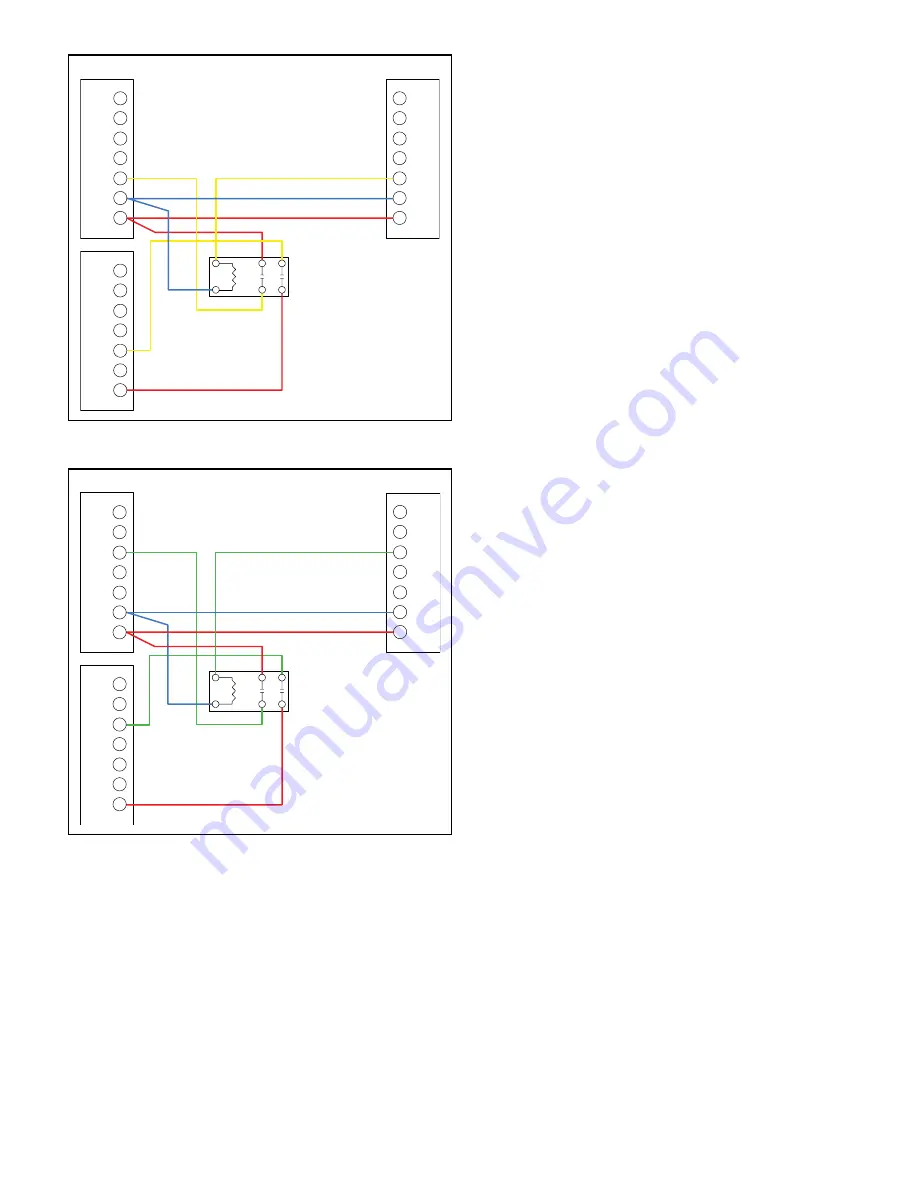
COOL TWIN ONLY
W1
R
C
Y1
Y2
G
W2
W1
R
C
Y1
Y2
G
W2
W1
R
C
Y1
Y2
G
W2
Figure 2.
FURNACE
1F
URNACE
2
ISO RELAY
THERMOST
AT
FAN TWIN ONLY
W1
R
C
Y1
Y2
G
W2
W1
R
C
Y1
Y2
G
W2
W1
R
C
Y1
Y2
G
W2
Figure 3.
Two-Stage Heating and Single-Stage Cooling with
Single-Stage Thermostat
1. Mount DPST relay(s) (supplied with kit) next to the
blower control board of Furnace 1. Use kit supplied
self-tapping screws to mount DPST relay(s) to the
control bracket.
2. Connect the thermostat with Furnace 1, Furnace 2,
and the DPST relays as shown in Figure 1 through
Figure 3. Use the female quick connect terminals
supplied in kit and the proper length of 18 gauge wire
(field supplied) to complete wiring.
3. Set DIP switches of Furnace 1 and Furnace 2 control
boards to same furnace mode DIP switch setting for
single stage thermostat, 2nd stage timing setting
and blower off setting. See the furnaces’ installation
instructions for additional detail.
NOTE:
Units are factory shipped with DIP switch
settings for two-stage thermostat operation.
4. After wiring is complete, cycle both high and low
heating modes and cooling modes to verify both are
working properly.


