background image

Page 25

SSB*H4 SERIES

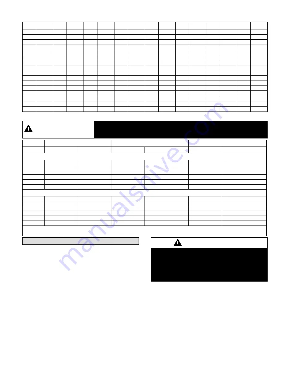
Table 3. HFC-410A Temperature (°F) - Pressure (Psig)

°F

Psig

°F

Psig

°F

Psig

°F

Psig

°F

Psig

°F

Psig

°F

Psig

°F

Psig

32

100.8

48

137.1

63

178.5

79

231.6

94

290.8

110

365.0

125

445.9

141

545.6

33

102.9

49

139.6

64

181.6

80

235.3

95

295.1

111

370.0

126

451.8

142

552.3

34

105.0

50

142.2

65

184.3

81

239.0

96

299.4

112

375.1

127

457.6

143

559.1

35

107.1

51

144.8

66

187.7

82

242.7

97

303.8

113

380.2

128

463.5

144

565.9

36

109.2

52

147.4

67

190.9

83

246.5

98

308.2

114

385.4

129

469.5

145

572.8

37

111.4

53

150.1

68

194.1

84

250.3

99

312.7

115

390.7

130

475.6

146

579.8

38

113.6

54

152.8

69

197.3

85

254.1

100

317.2

116

396.0

131

481.6

147

586.8

39

115.8

55

155.5

70

200.6

86

258.0

101

321.8

117

401.3

132

487.8

148

593.8

40

118.0

56

158.2

71

203.9

87

262.0

102

326.4

118

406.7

133

494.0

149

601.0

41

120.3

57

161.0

72

207.2

88

266.0

103

331.0

119

412.2

134

500.2

150

608.1

42

122.6

58

163.9

73

210.6

89

270.0

104

335.7

120

417.7

135

506.5

151

615.4

43

125.0

59

166.7

74

214.0

90

274.1

105

340.5

121

423.2

136

512.9

152

622.7

44

127.3

60

169.6

75

217.4

91

278.2

106

345.3

122

428.8

137

519.3

153

630.1

45

129.7

61

172.6

76

220.9

92

282.3

107

350.1

123

434.5

138

525.8

154

637.5

46

132.2

62

175.4

77

224.4

93

286.5

108

355.0

124

440.2

139

532.4

155

645.0

47

134.6

78

228.0

109

360.0

140

539.0

Table 4. Normal Operating Pressures (10 and S5 psig)

IMPORTANT

Use this table to perform maintenance checks; it is not a procedure for charging the system. Minor variations
in these pressures may be due to differences in installations. Significant deviations could mean that the
system is not properly charged or that a problem exists with some component in the system.

Model

SSB036H4S4

SSB048H4S4

SSB060H4S4

5

F (

5

C)*

Liquid

Suction

Liquid

Suction

Liquid

Suction

First Stage (Low Capacity)

65 (18)

217

141

229

140

229

134

75 (24)

251

143

263

143

264

138

85 (29)

292

146

304

146

305

140

95 (35)

337

147

350

148

349

142

105 (41)

387

150

400

150

402

147

115 (46)

440

154

453

155

455

149

Second Stage (High Capacity)

65 (18)

230

137

234

135

244

129

75 (24)

265

140

269

137

282

131

85 (29)

307

141

312

140

324

133

95 (35)

354

144

359

141

371

136

105 (41)

405

146

409

143

422

139

115 (46)

460

149

465

146

474

143

*Temperature of air entering outdoor coil.

**(10 psig; Vapor +5 psig) Typical pressures; indoor unit match up, indoor air quality equipment, and indoor load will cause the pressures to vary.

System Operation

SECOND-STAGE OPERATION

If the demand defrost control (A108) receives a call for
second-stage compressor operation Y2 in heating or
cooling mode and the first‐stage compressor output is
active, the second‐stage compressor solenoid output will
be energized.
If first‐stage compressor output is active in heating mode
and the outdoor ambient temperature is below the selected
compressor lock-in temperature, the second‐stage
compressor solenoid output will be energized without the
Y2 input. If the jumper is not connected to one of the
temperature selection pins on 

P3

 (40, 45, 50, 55°F), the

default lock-in temperature of 40°F (4.5°C) will be used.

IMPORTANT

Some scroll compressor have internal vacuum protector
that will unload scrolls when suction pressure goes
below 20 psig. A hissing sound will be heard when the
compressor is running unloaded. Protector will reset
when low pressure in system is raised above 40 psig. DO
NOT REPLACE COMPRESSOR.

Содержание SSB036H4S4

Страница 1: ...page 12 to avoid damaging the service valve s internal seals INSTALLATION INSTRUCTIONS S CLASS SSB H4 Units AIR CONDITIONER UNITS 507163 01 6 2013 Supersedes 506641 01 TABLE OF CONTENTS Shipping and...

Страница 2: ...45 1143 35 1 2 902 39 3 8 1001 16 7 8 429 8 3 4 222 3 1 8 79 30 3 4 781 4 5 8 117 3 3 4 95 26 7 8 683 Model Number Identification S S B Y 1 036 H 4 4 S Major Design Sequence A 1st Generation B 2nd Ge...

Страница 3: ...R DRIER SINGLE FLOW FIELD CONNECTION FOR LIQUID LINE SET LIQUID LINE SERVICE VALVE SUCTION LINE SERVICE VALVE FIELD CONNECTION FOR SUCTION LINE HIGH PRESSURE SWITCH MANUAL RESET S4 COMPRESSOR HARNESS...

Страница 4: ...nt loss during shipping and handling Using an Allen wrench rated at less than 50Rc risks rounding or breaking off the wrench or stripping the valve stem recess See the Lennox Service and Application N...

Страница 5: ...Access Service Port A service port cap protects the service port core from contamination and serves as the primary leak seal 1 Remove service port cap with an appropriately sized wrench 2 Connect gaug...

Страница 6: ...ressure ratio meets a certain value or when the suction pressure is as high as 20 psig Compressor suction pressures should never be allowed to go into a vacuum Prolonged operation at low suction press...

Страница 7: ...tion to a window see the provided illustration in figure 5 detail A PLACING UNIT ON SLAB When installing unit at grade level the top of the slab should be high enough above grade so that water from hi...

Страница 8: ...of two 2 degrees or two inches per five feet 50 mm per 1 5 m away from building structure MOUNTING SLAB BUILDING STRUCTURE GROUND LEVEL Outside Unit Placement Slab Mounting at Ground Level SAME FASTEN...

Страница 9: ...VERED PANEL REMOVAL Remove the louvered panels as follows 1 Remove two screws allowing the panel to swing open slightly 2 Hold the panel firmly throughout this procedure Rotate bottom corner of panel...

Страница 10: ...erant line sizes as listed in table 2 NOTE When installing refrigerant lines longer than 50 feet see the Lennox Refrigerant Piping Design and Fabrication Guidelines CORP 9351 L9 or contact Lennox Tech...

Страница 11: ...OR RAFTER AT 8 FEET 2 43 METERS INTERVALS THEN STRAP THE LIQUID LINE TO THE VAPOR LINE FLOOR JOIST OR ROOF RAFTER REFRIGERANT LINE SET INSTALLING HORIZONTAL RUNS NOTE Similar installation practices sh...

Страница 12: ...Perform operations only in well ventilated areas Wear gloves and protective goggles or face shield to protect against burns Wash hands with soap and water after handling brazing alloys and flux IMPORT...

Страница 13: ...AWAY FROM SERVICE VALVE Flow regulated nitrogen at 1 to 2 psig through the low side refrigeration gauge set into the liquid line service port valve and out of the suction vapor line service port valve...

Страница 14: ...ICE VALVES POINT FLAME AWAY FROM SERVICE VALVE PREPARATION FOR NEXT STEP 7 WARNING 1 FIRE PERSONAL INJURY OR PROPERTY DAMAGE will result if you do not wrap a wet cloth around both liquid and suction l...

Страница 15: ...ion valve and the two Teflon rings H Use a field provided fitting to temporary reconnect the liquid line to the indoor unit s liquid line orifice housing LOW HIGH EXISTING INDOOR UNIT GAUGE MANIFOLD I...

Страница 16: ...one of the provided Teflon rings around the stubbed end of the expansion valve and lightly lubricate the connector threads and expose surface of the Teflon ring with refrigerant oil D Attach the stub...

Страница 17: ...inder of HFC 410A refrigerant to the center port of the manifold gauge set Open the valve on the HFC 410A cylinder vapor only B Open the high pressure side of the manifold to allow HFC 410A into the l...

Страница 18: ...and indoor unit until the absolute pressure does not rise above 500 microns 29 9 inches of mercury within a 20 minute period after shutting off the vacuum pump and closing the manifold gauge valves F...

Страница 19: ...efer to the unit nameplate for minimum circuit ampacity and maximum fuse or circuit breaker HACR per NEC Install power wiring and properly sized disconnect switch NOTE Units are approved for use only...

Страница 20: ...Page 20 507163 01 05 13 Figure 14 Typical Wiring Diagram Y Voltage Figure 15 SSB H4 Typical Factory Diagram Y Voltage...

Страница 21: ...arge If the outdoor unit is void of refrigerant clean the system using the procedure described below 1 Leak check system using procedure outlined on page 17 2 Evacuate the system using procedure outli...

Страница 22: ...ition has been corrected 6 Set the thermostat for a cooling demand Turn on power to the indoor indoor unit and close the outdoor unit disconnect switch to start the unit 7 Recheck voltage while the un...

Страница 23: ...ir flow All temperatures are expressed in F Figure 19 Checking Indoor Airflow over Evaporator Coil using Delta T Chart WHEN TO CHARGE Warm weather best Can charge in colder weather CHARGE METHOD Deter...

Страница 24: ...t based upon line length SC Subcooling Values F 1 0 C 0 6 BLOCK OUTDOOR COIL sometimes necessary with lower temperatures Use cardboard or plastic sheet to restrict the airflow through the outdoor coil...

Страница 25: ...ions could mean that the system is not properly charged or that a problem exists with some component in the system Model SSB036H4S4 SSB048H4S4 SSB060H4S4 5F 5C Liquid Suction Liquid Suction Liquid Suc...

Страница 26: ...ry order another of like design and capacity The replacement filter drier must be suitable for use with HFC 410A refrigerant Maintenance DEALER Maintenance and service must be performed by a qualified...

Страница 27: ...r units are equipped with reusable foam filters Clean foam filters with a mild soap and water solution rinse thoroughly allow filter to dry completely before returning it to the unit or grille NOTE Th...

Страница 28: ...Liquid Higher Start Up and Performance Checklist Job Name Job no Date Job Location City State Installer City State Unit Model No Serial No Service Technician Nameplate Voltage Rated Load Ampacity Comp...

Отзывы: